System Controller WV-CU151 Before attempting to connect or operate this product, please read these instructions completely
ENGLISH VERSION We declare under our sole responsibility that the product to which this declaration relates is in conformity with the standards or other normative documents following the provisions of Directives EEC/73/23 and EEC/89/336. Vi erklærer os eneansvarlige for, at dette produkt, som denne deklaration omhandler, er i overensstemmelse med den følgende standarder eller andre normative dokumenter i følge bestemmelserne i direktivene 73/23/EEC og 89/336/EEC.
PREFACE ........................................................................................................................................................................................... 2 FEATURES ......................................................................................................................................................................................... 2 PRECAUTIONS .........................................................................................................
PREFACE FEATURES The Panasonic System Controller WV-CU151 is designed for use with the Combination Camera WV-CS600 / WVCS400 or Receiver WV-RC100 / WV-RC150 / WV-RC170. Multiplexed control signal on the video signal over a single coaxial cable saves the expense of wiring cost. The built-in alarm output connector allows to supply the alarm signal to the external equipment. 1. Setting and selection of the Program menu are available. 2.
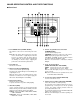
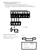
MAJOR OPERATING CONTROL AND THEIR FUNCTIONS ■ Front Panel System Controller WV-CU151 POWER BUSY POWER RESET ON SHIFT ; 1 ALARM l 2 3 5 6 UP OFF HOUSING WIPER PROS CAM MENU DEF 4 SET AUX 2 CLOSE IRIS OPEN 1 TELE ZOOM WIDE NEAR FOCUS FAR L 7 8 9 HOME 0 POSI R PAN RANDOM AUTO DOWN AF 1. Power ON/OFF Switch (POWER: ON/OFF) This switch is used to turn on and off the power of the unit.
15. Down Switch (8) This switch is used to move the cursor (on the Set up or Program Menu) in the down direction. 10. Auxiliary 1 / 2 Selection Switch (AUX: 1/2) Used to control the user’s auxiliary equipment. AUX1: Turn off the Shift Switch to select this position. AUX2: Turn on the Shift Switch to select this position. 16. Left Switch (4) This switch is used to move the cursor (on the Set up or Program Menu) in the left direction. 11.
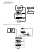
CONNECTIONS • Dip Switch Setting Before connecting this controller, confirm the Dip Switch Setting if the system setting change is required. The following setting procedure should be made by qualified service personnel or system installers. Preparation: Take off the bottom cover by removing the two fixing screws. Bottom Cover SW202 SW1 SW2 SW201 1. SW2 3. SW1 Set this switch (SW2) to choose the alarm reset output signal as either Open Collector (O.C.) or Pulse (VTR). Open Collector (O.C.
SYSTEM CONNECTION ■ Basic Connection WV-CS600 WV-CS600 Camera Site 1.
■ Application 2 Connection with the Time Lapse VTR • Connection of Alarm Output Terminal Make sure the polarity of the buzzer to meet with this terminal. The positive (+) terminal of the buzzer should be connected with the Alarm Output Terminal. The Alarm Output Terminal is composed of the Open Collector Output and the capacity is 16V DC, 100mA or less. (1) In case the buzzer is operable within the capacity of Alarm Output Terminal, connect buzzer as shown below.
OPERATING PROCEDURE Before starting the following procedures, all system components should be turned on. A. For the Combination Camera WV-CS600, WV-CS400, specified Pan/tilt Head or Receivers 1. Manual Panning / Tilting The panning should be controlled with a Joystick operation as shown below. Note: The panning / tilting speed is according to the angle of a Joystick as shown below. Up UP Right Left L R Left Right Up DOWN Down Down Low speed High speed 2. Automatic Panning 3.
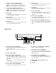
4. Preset Position Setting SHIFT 4-1. Press the preset number. 4-2. Press the POSI Switch. The camera is turned to the preset position. 1 2 3 4 5 6 LED lights on CLOSE IRIS OPEN TELE ZOOM WIDE To brighten To darken SET 7 8 9 HOME 0 POSI 1 2 Note: The control speed may be slow during the AGC setting in the camera side. c. Reset of Iris Level Allows the iris level to return into the initial one. c-1. Press SHIFT Switch. The LED on the SHIFT Switch lights. c-2.
7. Alarm 7-1. When the alarm signal is supplied in the Alarm On mode, “Alarm” is displayed on the screen of the monitor. (The Alarm display is preset to OFF at the factory.) 7-2. The LED on RESET Switch starts to blink and the buzzer sound comes. Alarm Character display RESET ALARM LED blinks. Notes: 1. Alarm Display On/Off and Buzzer On/Off mode can be selected. 2. The camera or receiver control can be continued even if the alarm signal is supplied. 8.
9. Program Menu Setting SHIFT a. Entering the Program Menu LED lights on a-1. Press the SHIFT Switch. The LED on the SHIFT Switch will light. PROS CAM MENU LED lights on a-2. Press PROG Switch more than 2 sec. The LED on the PROG Switch lights and the following menu is displayed on the monitor screen.
c. Controller Set Up Menu Description The setable items are shown in the following. Cable Comp Cable compensation S : The cable length is 0 m to 500 m or less. M : The cable length is 500 m to 900 m or less. L : The cable length is 900 m to 1200 m or less. (with 5C-2V) Alarm Time Alarm operating time (Self return time) 0.5, 1, 2, ...60, 65, ...120 sec.
4. Alarm Buzzer Setting 4-1. Move the cursor to “Alarm Buzzer” by using the Up / Down Switch. 4-2. Select the On / Off mode by using Right / Left Switch. e. Camera Set Up e-1. Press the Camera / Program Menu Selection Switch more than 2 sec. The LED of CAM MENU lights and the camera set up menu is displayed on the monitor screen. e-2. To close the camera set up menu, press the Camera / Program Menu Selection Switch. The LED of CAM MENU lights off and the camera set up menu is disappeared.
2-4. Press the Set Switch. “Loading” is appeared and blinking during the down load or up load. Notes: 1. The previous data should not be kept. After completing the up load or down load, “Cam1 : Save” and “End” are displayed on the down load or up load screen. 2. The up load or down load time is approx. 2 minutes per camera. After completing the up load or down load, the WV-CS600 will move to the Preset Position (REFRESH). 3. The down loading or up loading data should be the preset data only.
B. For the Housing C. For the External Equipment 1. Press the AUX Switch. When turning on the power of AUX2, press the SHIFT Switch. 1. Defroster Power On/Off 1-1. Press the HOUSING Switch. The LED on DEF Switch lights and the power of the defroster is turned on. Note: Confirm that the SHIFT Switch lights off. SHIFT LED lights off (AUX1 has been selected.) SHIFT LED lights off. AUX 2 HOUSING LED lights on 1 WIPER DEF LED lights on. SHIFT LED lights on (AUX2 has been selected.) 1-2.
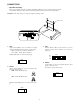
INSTALLATION Rack Mounting 2. Mount the Rear Panel onto the bottom by using the two mounting screws removed just before. Precaution: Keep the Power On/Off Switch turned off while making the following installations. The following procedures should be made by qualified service personnel or system installers. 3. Mount the Bottom Cover onto the rear by using the two mounting screws removed just before. 1.
Matsushita Electric Industrial Co., Ltd. Central P.O.