
Operating instructions


-7-
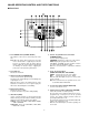
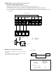
■ Cable-loss Compensation Setting
The maximum cable length in the system is approximately
1200 meter.
See the diagram below and set up the cable-loss compen-
sation switch for each unit accordingly.
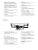
<For examples>
Camera
Camera WV-CU151
Am
ALARM
IN
OUT
GND
RESET
IN
RECOVER
OUT
GND
GND
GND RESET
OUT
RECOVER
IN
ALARM
OUT
ALARM
OUT
+12 V
NC
NO
C
Time Lapse VTR
Relay
To Alarm
NC: ON normally
NO: OFF normally
C: Common
■ Application 2 Connection with the Time Lapse VTR
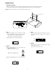
• Connection of Alarm Output Terminal
Make sure the polarity of the buzzer to meet with this terminal.
The positive (+) terminal of the buzzer should be connected with the Alarm Output Terminal.
The Alarm Output Terminal is composed of the Open Collector Output and the capacity is 16V DC, 100mA or less.
(1) In case the buzzer is operable within the capacity of Alarm Output Terminal, connect buzzer as shown below.
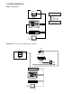
(2) In case the buzzer is not operable within the capacity of Alarm Output Terminal, the external relay unit should be used as
shown below.
Position of the
Cable comp of
Cable length program menu
(with 5C-2V) for WV-CU151
unit: meter
0 ≤ A < 500 S
500 ≤ A < 900 M
900 ≤ A < 1200 L