
Operating instructions


-4-
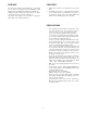
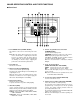
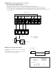
■ Rear Panel
VS/VD
IN/OUT
VIDEO
OUT
CAMERA
IN
RECOVER IN
NORMAL
ALARM
OFF
RESET
OUT
ALARM OUT
GND
10. Auxiliary 1 / 2 Selection Switch (AUX: 1/2)
Used to control the user’s auxiliary equipment.
AUX1: Turn off the Shift Switch to select this position.
AUX2: Turn on the Shift Switch to select this position.
11. Housing Switch (HOUSING: WIPER / DEF)
Used to control the wiper or defroster of the housing.
WIPER: Turn on the Shift Switch to select this position.
DEF: Turn off the Shift Switch to select this position.
12. Up Switch (2)
This switch is used to move the cursor (on the program
or camera menu) in the up direction.
13. Right Switch (6)
This switch is used to move the cursor (on the Set up
or Program Menu) in the right direction.
14. Set Switch (5)
The mode selected in the program or camera setup
menu is enabled by pressing this switch.
15. Down Switch (8)
This switch is used to move the cursor (on the Set up
or Program Menu) in the down direction.
16. Left Switch (4)
This switch is used to move the cursor (on the Set up
or Program Menu) in the left direction.
17. Position Switch (POSI)
Used to turn the pan/tilt head to the preset position.
Select the desired position in accordance with the pre-
set number.
18. Home Position Switch (HOME)
Used to turn the pan/tilt head to the home position of
the Combination Camera WV-CS600.
19. Joystick Controller (UP / DOWN / RIGHT / LEFT)
This is a joystick type switch. The specified pan/tilt
head can be controlled manually by moving this con-
troller.
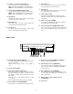
20. Alarm Output Terminal (ALARM OUT)
The alarm output signal is provided at this terminal for
the Time Lapse VTR.
(Open corrector output, 16V DC or less, 100mA or
less)
21. Ground Terminal (GND)
22. Reset Output Terminal (RESET OUT)
When the controller resets the activated alarm by
pressing the Alarm Reset Switch, the alarm reset out-
put signal is provided at this terminal for the Time
Lapse VTR.
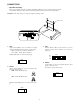
Note: Be sure to set the internal switch to the VTR
position.
Refer to the Dip switch Setting on page 5 for detail.
23. Recover Input Terminal (RECOVER IN)
Accepts the recover signal from the Time Lapse VTR.
24. Mode Selection Switch (NORMAL / ALARM OFF)
Used to select the activated mode.
25. Camera Input Connector (CAMERA IN)
This connector accepts the multiplexed video and con-
trol data signal from the WV-CS600, WV-CS400 or
specified receiver.
26. Video Output Connector (VIDEO OUT)
The composite video signal is provided at this connec-
tor. The control data signal does not include in the
video output signal.
27. External Gen-lock Input / Output Connector
(VS/VD IN/OUT)
28. Power Cord