
Operating instructions


-5-
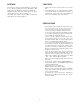
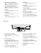
2. SW201
Set this switch (SW201) to choose the character dis-
play mode on the monitor.
NOR : White with Black border
REV : Black with White border
Initially, normal (NOR) position is selected at the facto-
ry.
3. SW1
Confirm switches (SW1) on the board are set to the
position as shown. These switches are used only for
factory test.
4. SW202
Set this switch to choose the External Gen-lock Input
signal as either VS or VD.
VS position is preset at the factory.
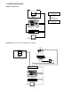
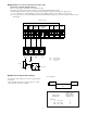
SW202 SW1
SW2 SW201
SW2
VTR O.C
SW201
REV NOR
8Bit
ON
OFF
SW1
1
SW202
VS VD
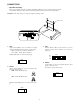
Bottom Cover
1. SW2
Set this switch (SW2) to choose the alarm reset output
signal as either Open Collector (O.C.) or Pulse (VTR).
Open Collector (O.C.): 16V DC 100mA max.
Pulse (VTR) : +5V DC approx. 500msec.
Initially, VTR position is selected at the factory.
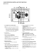
CONNECTIONS
• Dip Switch Setting
Before connecting this controller, confirm the Dip Switch Setting if the system setting change is required.
The following setting procedure should be made by qualified service personnel or system installers.
Preparation: Take off the bottom cover by removing the two fixing screws.