Getting Started Guide Catalyst 3550 Multilayer Switch Getting Started Guide INCLUDING LICENSE AND WARRANTY 1 About this Guide 2 Taking Out What You Need 3 Running Express Setup 4 Managing the Switch 5 Rack-Mounting 6 Connecting to DC Power 7 In Case of Difficulty 8 Obtaining Documentation 9 Obtaining Technical Assistance 10 Cisco Limited Lifetime Hardware Warranty Terms
1 About this Guide This guide provides instructions on how to use Express Setup to initially configure your Catalyst switch. Also covered are switch management options, basic rack-mounting procedures, port and module connections, power connection procedures for both AC- and DC-powered switches, and troubleshooting help. For additional installation and configuration information, and technical specifications, refer to the Catalyst 3550 documentation on Cisco.com.
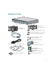
Shipping Box Contents SYSTEM RPS MODE STATUS UTIL DUPLX SPEED 1 2 3 4 Catalyst 5 6 3550 7 8 9 10 1 Catalyst 3550 switch Two 19-inch mounting brackets 2 Two 19-inch mounting brackets Four number-12 Phillips machine screws Four number-8 Phillips truss-head screws Six number-8 Phillips flat-head screws Connector cover for redundant power system (RPS) Console cable Two number-4 pan-head screws Cable guide AC power cord (AC-powered switches only) e nc ia on pl ati om rm h C o itc y Inf w or y e S
3 Running Express Setup When you first set up the switch, you should use Express Setup to enter the initial IP information. This enables the switch to connect to local routers and the Internet. You can then access the switch through the IP address for further configuration. To run Express Setup: Step 1 Verify that no devices are connected to the switch, because during Express Setup, the switch acts as a DHCP server.
Step 7 Connect a straight-through Category 5 Ethernet cable (not provided) to any 10/100 or 10/100/1000 Ethernet port on the switch front panel and to the Ethernet port on the PC. SYSTEM RPS MODE STATUS UTIL DUPLX SPEED 1 2 3 4 Catalyst 5 6 3550 7 8 9 10 1 2 DHCP-enabled PC Step 8 Verify that the LEDs on both Ethernet ports are green. Step 9 Wait 30 seconds. Step 10 Launch a web browser on your PC. Enter the IP address 10.0.0.1 in the web browser, and press Enter.
Step 12 Enter this information in the Network Settings fields: • In the Management Interface (VLAN ID) field, the default is 1. Enter a new VLAN ID only if you want to change the management interface through which you manage the switch and to which you assign IP information. The VLAN ID range is 1 to 1001. • In the IP Address field, enter the IP address of the switch. In the IP Subnet Mask field, click the drop-down arrow, and select an IP Subnet Mask.
Step 14 Click Submit to save your settings, or click Cancel to clear your settings. When you click Submit, the switch is configured and exits Express Setup mode. The PC displays a warning message and then attempts to connect with the new switch IP address. If you configured the switch with an IP address that is in a different subnet from the PC, connectivity between the PC and the switch is lost. Step 15 Disconnect the switch from the PC, and install the switch in your production network.
Downloading Cisco Network Assistant Cisco Network Assistant is a free software program that you download from Cisco.com and run on your PC. Network Assistant offers advanced options for configuring and monitoring multiple devices, including switches, switch clusters, switch stacks, routers, and access points. Follow these steps: 1. From the device manager page, select Network Assistant. 2. Follow the instructions to download the program to your PC. 3.
5 Rack-Mounting This section covers basic 19-inch rack-mounting and switch port connections. The illustrations in this section show the Catalyst 3550-12T and 3550-24 switch for examples. You can install and connect other Catalyst 3550 switches as shown in these illustrations. For alternate mounting procedures, such as installing the switch in a 24-inch rack or on a wall, and for additional cabling information, refer to the Catalyst 3550 Multilayer Switch Hardware Installation Guide on Cisco.com.
Installation Warning Statements This section includes the basic installation warning statements. Warning To prevent the switch from overheating, do not operate it in an area that exceeds the maximum recommended ambient temperature of 113˚F (45˚C). To prevent airflow restriction, allow at least 3 inches (7.6 cm) of clearance around the ventilation openings. Statement 17B Warning This equipment is intended to be grounded. Ensure that the host is connected to earth ground during normal use.
Warning Installation of the equipment must comply with local and national electrical codes. Statement 1074 Warning Statements for Connecting to DC Power These statements apply when connecting a Catalyst 3550-24-DC switch to DC power. Warning When installing the unit, always make the ground connection first and disconnect it last. Statement 42 Warning An exposed wire lead from a DC-input power source can conduct harmful levels of electricity.
Attaching the Brackets Use four Phillips flat-head screws to attach the long side of the brackets on the Catalyst 3550-12 switches.
Attaching the Brackets Use six Phillips flat-head screws to attach the long side of the brackets on the Catalyst 3550-24 and 3550-48 switches.
Rack-Mount the Switch Use the black Phillips machine screw to attach the cable guide to the left or right bracket. Use the four number-12 Phillips machine screws to attach the brackets to the rack.
Connect to the Switch Ports This section describes how to connect to the fixed switch ports and to the GBIC module ports. Connect to 10/100 and 10/100/1000 Ports Follow these steps: Step 1 Step 2 When you connect to servers, workstations, IP phones, wireless access points, and routers, insert a straight-through, twisted four-pair, Category 5 cable in a switch 10/1001 or 10/100/1000 port. Use a crossover, twisted four-pair, Category 5 cable when you connect to other switches, hubs, or repeaters.
Connect to 100BASE-FX Ports Follow these steps: Step 1 Remove the dust plugs from the 100BASE-FX ports and the rubber caps from the MT-RJ patch cable. Store them for future use. SYSTEM RPS 1X 2X STATUS MODE UTIL DUPLX SPEED 3X 4X 5X 6X 7X 8X 100BASE-FX ports Step 2 Insert an appropriate cable into a 100BASE-FX port. Insert the other cable end into an SC or ST port on the other device.
After you connect to the switch port, the port LED turns amber while the switch establishes a link. This process takes about 30 seconds, and then the LED turns green when the switch and the target device have an established link. If the LED is off, the target device might not be turned on, there might be a cable problem, or there might be a problem with the adapter installed in the target device. See the “In Case of Difficulty” section on page 20 for information about online assistance.
Step 3 Slide the exposed area of the 6-gauge wire into the ground lug, and use the crimping tool to crimp the lug to the wire. Step 4 Using the ratcheting screwdriver, torque the ground lug screws to 15 lbf-in. (240 ounce-force inches [ozf-in.]) to attach the ground lug to the switch. Wiring the DC Input Power Source Follow these steps: Step 1 On the terminal block connector, identify the positive and negative feed positions. Step 2 Strip each of the four wires coming from the DC power source to 0.
Step 4 Step 5 Using the ratcheting torque screwdriver, torque each terminal block captive screw (above the installed wire leads) to 4.5 lbf-in. (72 ozf-in.). Return Negative Return Negative Feed A Feed B Insert the terminal block plug in the terminal block header on the rear panel of the switch. 36 - 72V 1 - 0.5A A B Step 6 Caution Move the circuit-breaker handle for the DC power source to the on position.
7 In Case of Difficulty If you experience difficulty, help is available here and on Cisco.com. This section includes Express Setup troubleshooting, how to reset the switch, how to access help online, and where to find more information.
Resetting the Switch This section describes how to reset the switch by rerunning Express Setup. These are reasons why you might want to reset the switch: • You installed the switch in your network and cannot connect to it because you assigned the wrong IP address. • You want to clear all configuration from the switch and assign a new IP address.
Follow these steps: 1. Open your browser, and go to http://www.cisco.com/. 2. Click Technical Support. 3. Click Product Support > Switches > Catalyst LAN and ATM Switches > 3550 Series Switches > Troubleshooting. 4. Click the subject that addresses the problem that you are experiencing. For More Information For more information about the switch, refer to these documents on Cisco.com: • Catalyst 3550 Multilayer Switch Hardware Installation Guide (not orderable but available on Cisco.com).
8 Obtaining Documentation Cisco documentation and additional literature are available on Cisco.com. Cisco also provides several ways to obtain technical assistance and other technical resources. These sections explain how to obtain technical information from Cisco Systems. Cisco.com You can access the most current Cisco documentation at this URL: http://www.cisco.com/univercd/home/home.htm You can access the Cisco website at this URL: http://www.cisco.
You can submit comments by using the response card (if present) behind the front cover of your document or by writing to the following address: Cisco Systems Attn: Customer Document Ordering 170 West Tasman Drive San Jose, CA 95134-9883 We appreciate your comments. 9 Obtaining Technical Assistance For all customers, partners, resellers, and distributors who hold valid Cisco service contracts, Cisco Technical Support provides 24-hour-a-day, award-winning technical assistance.
Submitting a Service Request Using the online TAC Service Request Tool is the fastest way to open S3 and S4 service requests. (S3 and S4 service requests are those in which your network is minimally impaired or for which you require product information.) After you describe your situation, the TAC Service Request Tool provides recommended solutions. If your issue is not resolved using the recommended resources, your service request is assigned to a Cisco TAC engineer.
Obtaining Additional Publications and Information Information about Cisco products, technologies, and network solutions is available from various online and printed sources. • Cisco Marketplace provides a variety of Cisco books, reference guides, and logo merchandise. Visit Cisco Marketplace, the company store, at this URL: http://www.cisco.com/go/marketplace/ • The Cisco Product Catalog describes the networking products offered by Cisco Systems, as well as ordering and customer support services.
10 Cisco Limited Lifetime Hardware Warranty Terms There are special terms applicable to your hardware warranty and various services that you can use during the warranty period. Your formal Warranty Statement, including the warranties and license agreements applicable to Cisco software, is available on Cisco.com. Follow these steps to access and download the Cisco Information Packet and your warranty and license agreements from Cisco.com. 1. Launch your browser, and go to this URL: http://www.cisco.
Duration of Hardware Warranty A Cisco product hardware warranty is supported for as long as the original end user continues to own or use the product, provided that the fan and power supply warranty is limited to five (5) years. In the event of a discontinuance of product manufacture, the Cisco warranty support is limited to five (5) years from the announcement of the discontinuance.
Corporate Headquarters Cisco Systems, Inc. 170 West Tasman Drive San Jose, CA 95134-1706 USA www.cisco.com Tel: 408 526-4000 800 553-NETS (6387) Fax: 408 526-4100 European Headquarters Cisco Systems International BV Haarlerbergpark Haarlerbergweg 13-19 1101 CH Amsterdam The Netherlands www-europe.cisco.com Tel: 31 0 20 357 1000 Fax: 31 0 20 357 1100 Americas Headquarters Cisco Systems, Inc. 170 West Tasman Drive San Jose, CA 95134-1706 USA www.cisco.