
Multilayer Switch Started Guide Catalyst 3550

15
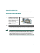
Connect to the Switch Ports
This section describes how to connect to the fixed switch ports and to the GBIC module ports.
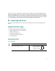
Connect to 10/100 and 10/100/1000 Ports
Follow these steps:
Warning
Voltages that present a shock hazard may exist on Power over Ethernet (PoE) circuits if
interconnections are made using uninsulated exposed metal contacts, conductors, or
terminals. Avoid using such interconnection methods, unless the exposed metal parts
are located within a restricted access location and users and service people who are
authorized within the restricted access location are made aware of the hazard. A
restricted access area can be accessed only through the use of a special tool, lock and
key or other means of security. Statement 1072
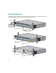
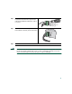
Step 1
When you connect to servers,
workstations, IP phones, wireless
access points, and routers, insert a
straight-through, twisted four-pair,
Category 5 cable in a switch
10/100
1
or10/100/1000 port. Use a
crossover, twisted four-pair,
Category 5 cable when you connect
to other switches, hubs, or
repeaters.
1. The Catalyst 3550-24PWR switch 10/100 inline power ports, also referred to as pre-standard Power over
Ethernet (PoE) ports, provide –48 VDC power and protocol support for Cisco IP Phones and Cisco Aironet
Access points. See the hardware installation guide on Cisco.com for more information about PoE ports.
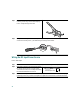
Step 2
Insert the other cable end into an RJ-45 connector on the other device.
MODE
SYSTEM
1X
2X
11X
12X
RPS
STATUS
UTIL
DUPLX
SPEED
1
2
3
4
5
6
7
8
9
10
11
12
10/100 or 10/100/1000 ports