
Installation Guide


3
Form 42-47-00-00 version 7
© 2018 Paragon Pro Manufacturing Solutions, Inc. All Rights Reserved
CABLE REPLACEMENT INSTRUCTIONS continued
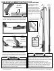
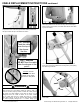
6b. With a clock-wise motion like that of tightening a screw driver,
twist the cable installation tool while holding the crimped end of
the cable up into the sheave pocket. The cable will pop loose
from the tool and pop up through the sheave pocket as shown in
this cut away view.
The cable MUST feed in from the top of the “B” exactly as
shown in steps 2 - 3 in order to function properly. Failure to
install the cable correctly as shown can cause wearing of the
cable for which it is not designed which can result in failure of
the cable. Failure of the cable while the lift is raised will result
in a sudden and rapid lowering of the lift and the load possibly
resulting in serious property damage and/or serious bodily injury.
WARNING
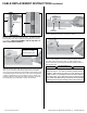
6a. Insert the crimped end of the cable into the sheave pocket at
the end nearest the end of the “B” section as shown.
YES-Correct
Sheave Pocket
NO!!
WRONG!!
X
“B” Section
5. Use the special tool provided to insert the crimped end of the
cable into the TOP end of the “B” section as shown in this cut away
view. If your “B” section is the factory original and not a replace-
ment, the top is the painted end and the bottom has several inches
of unfinished surface. If both ends of your “B” section are painted it
is either a replacement or you are working on the “F” section of an
extension 186-00. In either of these cases wear marks on the sec-
tion should give you an indication of which end is the top.
There should not be
more than 1” of cable
extending beyond tool.
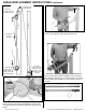
4a. Feed the crimped end of the new cable through the “A” sec-
tion anchoring “V” from the bottom as shown. 4b. Make sure the
anchoring end of the cable is pulled snugly against the anchoring
“V” as shown. (NEVER DISASSEMBLE THE NUT AND BOLT OF
CABLE ANCHORING ASSEMBLY)
“A” Section
Anchoring “V”
4a 4b