
Installation Guide

4
Form 42-47-00-00 version 7
© 2018 Paragon Pro Manufacturing Solutions, Inc. All Rights Reserved
CABLE REPLACEMENT INSTRUCTIONS continued
WARNING
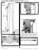
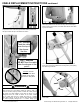
• DO NOT feed the cable through the areas marked “X” in the
photo above. Doing so will cause wearing of the cable for which
it was not designed which can result in failure of the cable.
Failure of the cable while the lift is raised will result in a sudden
and rapid lowering of the lift and load possibly resulting in serious
property damage and/or serious bodily injury.
• Failure to install the cable correctly as shown in these
instructions can cause wearing of the cable for which it is not
designed which can result in failure of the cable. Failure of the
cable while the lift is raised will result in a sudden and rapid
lowering of the lift and the load possibly resulting in serious
property damage and/or serious bodily injury.
(1)
(2)
(3)
(4)
(5)
“A”
Section
“B”
Section
DO NOT
Feed the cable
through these
openings in the
sheave pockets
marked “X”
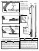
9. A correctly strung cable is
shown at right:
Starting through the “A” section
anchoring “V” from the bottom (1),
into the top of the “B” section (2),
back out through the sheave pocket
at the end nearest the top of the
telescoping section (3), into the slot
of the “B” section (4), and out a final
time through the end of the sheave
pocket nearest the bottom of the “B”
section (5).
You’re now ready to reassemble the
“A” section into the “B” section as
shown here:
X
X
7. Feed the crimped end of the cable down into the slot (a) of the
“B” section and out the bottom end of the telescoping section (b)
as shown. Pull the cable completely through to remove the slack.
X
X
(a)
(b)
DO NOT
Feed into the
sheave pocket
at these points!!
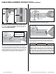
8a. Reload and insert the cable installation tool into the BOTTOM
end of the “B” section as shown.
8b. Repeat the process performed in steps 2 - 3: Insert the
crimped end of the cable up into the end of the sheave pocket
at the end nearest the bottom of the “B” section as traced by the
dotted arrows. Twist the installation tool while holding the crimped
end of the cable up into the sheave pocket. Pull the crimped end
out completely to remove the slack.
YES-Correct
Feed out through this
side of sheave pocket
WARNING
The cable MUST first pass down through the slot and out the bottom,
then loop back in from the bottom of the “B” to feed through the sheave
pocket exactly as shown in steps 4 - 5 in order to function properly.
Failure to install the cable correctly as shown can cause wearing of
the cable for which it is not designed which can result in failure of the
cable. Failure of the cable while the lift is raised will result in a sudden
and rapid lowering of the lift and the load possibly resulting in serious
property damage and / or serious bodily injury.
NO!! -
WRONG!!
DO NOT feed
out through
this side of the
sheave pocket!
X