
Network Device User's Guide


Installation
2-4
3166-A2-GB20-10
November 1998
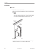
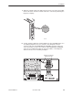
7. Attach a modular cable (not included) to the COM connector of the rear
connector module. (See Appendix D,
Pin Assignments
,
for detailed cable and
connector information.) Connect the other end to a terminal or PC.
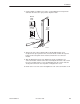
Terminal or PC
PORT 1
COM
98-16079
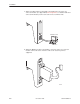
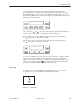
8. Attach the DB25 port cable to the PORT 1 connector on the rear connector
module. Connect the other end of the cable to the customer premises
equipment.
PORT 1
COM
DIAGNOSTIC
CHANNEL
DTE
98-16078