
Network Device User's Guide


SDCP Operation
3-11
3166-A2-GB20-10
November 1998
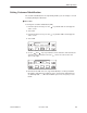
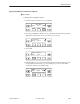
If you chose Prt1, the Port 1 LEDs screen lists the LED signals, two at a time,
on the second line. A vertical bar at the left of the LED name indicates the
condition is ON, while an underscore indicates the condition is Off.
F1
Port
n
LEDs:
JDTR _TXD
F2
F3
5. Use the and keys to scroll LED names onto the screen.
Changing Configuration Options
The DSU/CSU is an intelligent device that displays only valid options for the
current configuration. Therefore, you are only presented with menu choices that
are consistent with the current configuration and operational state of the
DSU/CSU; invalid combinations of configuration options do not appear. Be aware
that although all options are shown in this guide, what you see on your DSU/CSU
varies with your configuration.
The DSU/CSU offers configuration options located in the following memory areas:
H Active (Activ) – This is the configuration option set currently active for the
DSU/CSU. Before a configuration option set becomes active for the
DSU/CSU, you must save the set to the Active area. When the DSU/CSU is
shipped from the factory, the Active configuration option set is identical to the
Factory set. This area can be written to and controls the current operation of
the device.
H Customer 1 (Cust1) – This is the first of two sets of customer-defined
configuration options. This area can be written to.
H Customer 2 (Cust2) – This is the second of two sets of customer-defined
configuration options. This area can be written to.
H Factory 1 (Fact1) – This is a set of configuration options preset at the
factory. This set is determined by what is considered to be the most common
configuration used in the DSU/CSU market. Factory 1 options are read-only.
H Factory 2 (Fact2) – This is a set of configuration options preset at the
factory. This set is determined by what is considered to be the second most
common configuration used in the DSU/CSU market. Factory 2 options are
read-only.