Hotwire® ReachDSL™ Modem, Model 6350-A4 with Inline Phone Filter Installation Instructions Document Number 6350-A2-GN12-00 September 2001 Contents Hotwire 6350 ReachDSL Modem Overview ................................................. 1 Getting Started .............................................................................................. 4 Installing the Hotwire 6350 ReachDSL Modem ............................................ 5 Power-On .........................................................
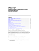
Hotwire ReachDSL System Copper pairs run from the central office (CO) to the customer premises (CP) to create the local loop. The local loop terminates on the customer premises at the demarcation point.
Phone Filter Depending on the type of phone handset and the quality of the home or business wiring, a phone filter is recommended to minimize background noise during a phone conversation. An internal phone filter is included with the Hotwire 6350 ReachDSL Modem. If additional telephones are used on the same phone line as the ReachDSL modem, install one phone filter on each telephone. There are two Hotwire phone filters: Hotwire 6035 Universal Phone Filter is designed for use with a tabletop phone.
Getting Started Before beginning your modem’s installation, make sure that you have all the equipment that you need. Package Checklist Verify that your package contains the following: ❑ Hotwire 6350 ReachDSL Modem ❑ DSL interface cable with RJ11 connectors ❑ Power cord with power transformer Be sure to register your warranty at www.paradyne.com/warranty.
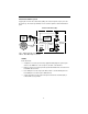
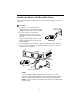
Installing the Hotwire 6350 ReachDSL Modem Place the Hotwire 6350 ReachDSL Modem on a flat surface with clearance for the rear connectors. Procedure 1. If a telephone is connected at the RJ11 wall jack where the modem will be installed, unplug the telephone line from the wall jack. RJ11 Wall Jack 2. Connect a telephone to the modem. (Optional – go to Step 3 if you are not connecting a telephone to the ReachDSL modem.
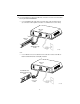
4. Use an 8-pin Ethernet cable for the Ethernet connection. Insert one end of the cable into the jack labeled ETHERNET. — Use a straight-through cable and connect the other end to an Ethernet hub. (To connect to a hub’s Uplink connection, use an Ethernet crossover cable).
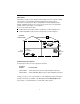
5. Insert the supplied power cord’s round end into the jack labeled POWER. Plug the transformer into an AC outlet. Power Jack POWE R ETHER NET PHON E LIN E Transformer or 01-17010 The ReachDSL modem hardware installation is now complete. When the power cord is installed, the ReachDSL modem goes through a power-on self-test. Power-On When power is applied, the ReachDSL modem performs self-diagnostics and the PWR LED is on.
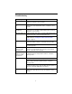
Status LEDs All of the LEDs turn on and off during the power-on self-test. After a successful self-test, the LEDs should appear as indicated in BOLD in the Condition column below. LED Condition Status PWR ON ReachDSL modem has power. ALM OFF No active alarms. ON An alarm condition exists. OFF No active tests. ON The TST LED is on during the power-on self-test and during a test initiated by the service provider. ON The DSL link is active and ready to transmit and receive data.
Troubleshooting LED Symptom Action All LEDs are on. If LEDs remain on after ten minutes, the modem is not functional. Contact the service provider. ALM LED remains on. The power-on self-test may have failed. Unplug the unit and reapply power. If the alarm LED is still on, contact the service provider. ALM and TST LEDs are blinking. Firmware download may be in progress. If firmware download is not in progress or the LEDs continue blinking after ten minutes, contact the service provider.
To improve data transmission throughput and minimize background noise during a telephone conversation, make sure that: The Hotwire 6350 ReachDSL Modem is always powered on, even when not in use, and A Hotwire phone filter is installed on every telephone on the same line as the Hotwire 6350 ReachDSL Modem (see Phone Filter on page 3). Increasing the Number of End-User Systems A single end-user system is attached to the Hotwire 6350 ReachDSL Modem by using an Ethernet crossover cable.
Cables & Connectors This section is reference information. Standard twisted-pair CAT3 or better cables are recommended. The LINE and PHONE interface connectors use 6-pin, non-keyed modular plugs. RJ11 or RJ14 6-pin connectors can be used. 6-Pin RJ11 Plugs Line & Phone Connectors Pin # Function 1 Not used 2 Ring 2 (optional) 3 DSL Ring 1 4 DSL Tip 1 5 Tip 2 (optional) 6 Not used Pin #6 Pin #1 98-15304a The LINE and PHONE jack pinouts are either filtered or unfiltered for POTS.
The Ethernet interface connector uses an 8-pin, non-keyed modular plug. — To connect the DSL modem to an Ethernet hub, use the straight-through connection. Ethernet Cable 8-Pin Straight-through Connection Pin # Function 1 10BaseT TX D+ 2 10BaseT TX D– 3 10BaseT RX D+ 4&5 6 7&8 8-Pin Plug Not used Pin #8 10BaseT RX D– Pin #1 98-16055a Not used –or– — To connect the DSL modem directly to a PC with an Ethernet NIC card, use an Ethernet crossover cable.
Optional ReachDSL Modem Wall Placement The Hotwire 6350 ReachDSL Modem is designed for tabletop placement. The modem can also be mounted on a wall. To mount the modem, you will need: ❑ Two slotted-head #6 self-threading screws with plastic anchors ❑ Drill and 3/16" drill bit for the plastic anchors ❑ Screwdriver A template with the dimensions for the two screws is provided. See ReachDSL Modem Hardware Template on page 14. Procedure To mount the Hotwire 6350 ReachDSL Modem: 1.
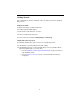
Bottom 5.
Technical Specifications for Hotwire 6350 ReachDSL Modem Item Specification* Height x Width x Depth 1.46" x 5.72" x 4.33" (3.71 cm x 14.54 cm x 11.00 cm) Weight 0.45 lb. (0.20 kg) Power Class 2 Transformer normal service input voltage range Input: 100 VAC (+10%), 50 Hz; 120 VAC (+10%), 60 Hz; or 230 VAC (+10%), 50/60 Hz Output: 5 VDC nominal, minimum 0.
! Important Safety Instructions 1. Read and follow all warning notices and instructions marked on the product or included in the manual. 2. Slots and openings in the cabinet are provided for ventilation. To ensure reliable operation of the product and to protect it from overheating, these slots and openings must not be blocked or covered. 3. Do not allow anything to rest on the power cord and do not locate the product where persons will walk on the power cord. 4.
CE Marking When the product is marked with the CE mark on the equipment label, this demonstrates full compliance with the following European Directives: Directive 73/23/EEC – Council Directive of 19 February 1973 on the harmonization of the laws of the member states relating to electrical equipment designed for use within states relating to electrical equipment designed for use within certain voltage limits, as amended by Directive 93/68/EEC.
Declaration of Conformity This Declaration of Conformity is made by Paradyne Corporation pursuant to Parts 2 and 15 of the Federal Communications Commission’s Rules. This compliance information statement pertains to the following products: Trade Name: Hotwire Model Number: 6350-A4-200 This device complies with Part 15 of the FCC Rules.
Supplier’s Declaration of Conformity Place of Issue: Paradyne Corporation 8545 126th Avenue North Largo, FL 33773-1502 USA Date of Issue: 8/17/2001 Paradyne Corporation, located at the above address, hereby certifies that the Hotwire® ReachDSL™ Model Number 6350-A4-200, bearing labeling identification number US:AW2DL03B6350-A4 complies with: the Federal Communications Commission’s (“FCC”) Rules and Regulations 47 CFR Part 68, the Administrative Council on Terminal Attachments (“ACTA”)-adopted technical cr
Government Requirements Certain governments require that instructions pertaining to connection to the telephone network be included in the installation and operation manual. Specific instructions are listed in the following sections. United States – Notice to Users of the Telephone Network 1. This equipment complies with Part 68 of the FCC rules. On the equipment is a label that contains, among other information, the FCC approval number which includes the Ringer Equivalence Number (REN) for this equipment.
8. This equipment cannot be used on public coin service provided by the telephone company. Connection to Party Line Service is subject to state tariffs. (Contact the state public utility commission, public service commission or corporation commission for information.) 9. An FCC compliant telephone cord with modular plugs may be provided with this equipment. This equipment is designed to be connected to the telephone network or premises wiring using a compatible modular jack which is Part 68 compliant.
Warranty, Sales, Service, and Training Information Contact your local sales representative, service representative, or distributor directly for any help needed. For additional information concerning warranty, sales, service, repair, installation, documentation, training, distributor locations, or Paradyne worldwide office locations, use one of the following methods: Internet: Visit the Paradyne World Wide Web site at www.paradyne.com. (Be sure to register your warranty at www.paradyne.com/warranty.
" *6350-A2-GN12-00*