
Network Card User Manual


8400-A2-GZ40-10 October 2003 3
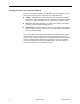
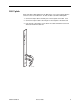
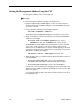
Installing the SCP Card
SCP cards can be installed in:
Slot A, Slot B, or both, of the 8820 GranDSLAM
Slot A of the 8620 GranDSLAM
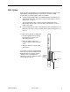
Procedure
To install the Hotwire SCP Card in a GranDSLAM chassis:
1. If there is a filler plate covering the slot, remove it.
2. Remove the yellow screw covers.
3. Insert the card into the card guides of the slot on the chassis.
4. Carefully slide the card into the slot until the card meets the connectors on the
backplane. Then press in on the insertion/ejection levers until the card is fully
seated.
5. Verify that the SYSTEM Active or Standby indicator on the card’s faceplate is
cycling off and on. See SCP Card LEDs on page 8.
6. Secure the card by fastening the screws on each end of the faceplate. This is
required to maintain proper gasket pressure on the faceplate as well as proper
air flow.
7. Attach appropriate connections to the uplink. These are described in the
following sections:
— DS3 Uplink on page 5
— OC3 Uplink on page 6
— IMA Uplink on page 7
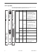
A
L
AR
M
S
M
a
jo
r
M
in
or
F
a
n
B
A
P
O
W
E
R
S
E
R
IA
L
S
M
C
M
C
L
O
C
K
A
A
L
A
R
M
2
4
6
8
1
0
1
2
14
1
6
1
8
1
3
5
7
9
1
1
13 1
5
1
7
L
A
N
/W
A
N
S
L
O
T
B
C
L
O
C
K
B
A
S
E
R
IA
L
M
C
C
A
C
A
L
A
R
M
48V RTN
48V NEG
P
O
W
E
R
E
N
T
R
Y
M
O
D
U
L
E
L
E
F
T
U
N
I
T
:
L
IN
E
A
R
IG
H
T
U
N
I
T
:
L
IN
E
B
W
AR
N
IN
G
!
POWER MUST BE DISCONNECTED AT THE SOURCE
BEFORE REMOVING OR INSTALLING THIS PWR ENTRY MODULE
48V RTN
48V NEG
P
O
W
E
R
E
N
T
R
Y
M
O
D
U
L
E
L
E
F
T
U
N
IT
:
L
IN
E
A
R
I
G
H
T
U
N
IT
:
L
IN
E
B
W
A
RN
ING
!
POWER MUST BE DISCONNECTED AT THE SOURCE
BEFORE REMOVING OR INSTALLING THIS PWR ENTRY MODULE
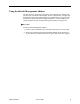
DSL
S
Y
S
T
E
M
O
K
A
lm
T
e
s
t
E
T
H
E
R
N
E
T
T
X
R
X
C
o
l
l
D
S
L
P
O
R
T
1
2
3
4
MCP
S
Y
S
T
E
M
O
K
A
lm
T
e
s
t
E
T
H
E
R
N
E
T
T
X
R
X
C
o
ll
SCM
S
Y
S
T
E
M
O
K
A
lm
T
e
s
t
E
T
H
E
R
N
E
T
T
X
R
X
C
o
ll
Slot A
03-17423