
Network Card User Manual


8400-A2-GZ40-10 October 2003 7
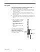
IMA Uplink
SCP cards with an IMA uplink have an RJ45M-type 50-position connector with
eight Tip/Ring and eight Tip1/Ring1 connections that conforms to ANSI
T1.403-1999. The following splitter cables are available:
Feature Number 8026-F1-001 for the Model 8416 SCP card terminates in
eight 8-pin modular jacks. See Table 2, Feature Number 8026-F1-001 Pin
Assignments, on page 12.
To connect the SCP card to a switch, attach the modular jacks of the
8026-F1-001 cable to T1/E1 crossover cables, and attach the crossover
cables to the switch.
Feature Number 8027-F1-001 for the Model 8417 SCP card terminates in 16
BNC jacks. See Table 3, Feature Number 8027-F1-001 Pin Assignments, on
page 13.
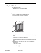
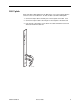
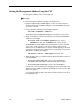
To cable an SCP card with an IMA uplink:
1. Feed the supplied cable tie through
the openings in the base of the
50-position connector.
2. Fasten the splitter cable to the
connector with the captive panhead
screw.
3. Wrap the cable tie around the cable
and fasten it.
If any ferrite chokes are supplied with the
SCP card, they must be installed to meet
EMI requirements. Install the choke or
chokes as close as possible to the
50-position connector. Hold them in place
with an adjacent cable tie.
03-17422
Cable Tie
Panhead Screw
Supplied
Cable Tie
Mount
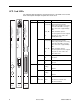
S
YSTEM
Active
Standby
Alarm
TX
RX
ETH
ER
N
ET
Test
U
PLIN
K
LK1
LK2
LK3
LK4
LK5
LK6
LK7
LK8
SCP-IMA
8417