
Corporation Network Card User Manual


part number V150LA20A for 120 VAC input and part number
V275LA20A for 208/240 VAC input.
NOTE: Sensor and valve wires may be extended for remote appli-
cations. Waterproof butt connectors should be used, and the cable
should be at least 16 gauge. Care must be taken to ensure a good splice
and that the individual wires are correctly identified. For remote
installation where the sensors are located more than 25 ft. from the
controller, contact Sporlan Division of Parker for guidance.
OPERATION
When first powered up the numeric display will show actual superheat
for Circuit 1.
1. The controller may be toggled between settings for Circuit 1 and 2
by pressing PB1 (left button).
2. When Circuit 1 is being displayed, the small Green LED will be lit.
3. When Circuit 2 is being displayed, the small Red LED will be lit.
4. If Circuit 2 is not being used its display and setting will show “00”.
5. PB2 will toggle the readings as follows and the small Green LED
will be steady or flash:
•ActualSuperheat,LEDconstant.
•Valvepercentageopen,LEDslowflash.
6. To change superheat set point for Valve 1:
•MakesurethedisplayshowsthesuperheatofValve1.
•PressandholdPB1andPB2for8seconds,LEDwillflashrapidly.
•UsePB1toincrementsetpoint.
•UsePB2todecrementsetpoint.
•PressandholdPB1andPB2for5secondstolockinsetpointand
return to actual superheat.
•TosetsuperheatforValve2togglePB1toValve2superheatand
repeat above.
7. To manually change valve position:
•ScrolltovalvepositionreadingwithPB2.
•PressandholdPB1andPB2simultaneouslyfor8seconds,Green
LED will flash rapidly.
•Increment“valveopen”percentagebypressingPB1for1second.
•Decrement“valveopen”percentagebypressingPB2for1second.
Valve will maintain manual open position for 1 hour or until PB1
and PB2 are pressed simultaneously and held for 5 seconds.
REMOTE PANEL DISPLAY
A remote panel display is available that will allow access to all the param-
eters of the controller. The Remote Panel Display can be used as a set
point tool in production, a diagnostic tool in the field or as a permanent
readout device for the controller. A five-foot cable is included.
Plug the remote display into the telephone jack (J9) on the controller. The
following is a list of readings available:
SUP1 Superheat read by controller for AC circuit 1
POS1 Number of steps valve is open (0-6386) for AC circuit 1
PRS1 Pressure read by the transducer (0-153 psi gauge) for AC
circuit 1
TMP1 Temperature read by the temperature sensor (-50 to 103°F) for
AC circuit 1
TST1 Saturated temperature for AC circuit 1
AC1, PDN1
AC1 when in normal operation
PDN1 when in pumpdown for AC circuit 1
R22, 134A, 407C, 404A, 507
R22 for refrigerant R-22, 134A for refrigerant R-134a, 407C
for refrigerant R-407C, and 404A for refrigerant R-404A and
R507 for refrigerant R-507. Note: Not all controllers have
both R-507 and R-407C.
LGE1, SML1, MED1, ESX1, S251
LGE1 if the EEV used is an SEI-50 or larger for AC circuit 1.
SML1 if the EEV used is smaller than an SEI-25 for AC circuit 1.
MED1 if the EEV used is a SEI-25 for AC circuit 1.
ESX1 if the EEV used is a ESX for AC circuit 1.
S251 if the EEV is an SER 1.5 to 20.
SSP1 Superheat set point (0 to 16°F) for AC circuit 1. Default is 10°F.
MOP1 Maximum operating suction pressure set point (0 to 153 PSI)
for AC circuit 1. Default is 153 PSI.
CTS1 Cut out suction pressure set point for AC circuit 1 (0 to 153 PSI)
CLP1 Calibrate pressure transducer for AC circuit 1.
CLT1 Calibrate temperature sensor for AC circuit 1.
PRO1 Proportional gain set point for AC circuit 1. Number of steps per
degree that superheat is above or below the superheat set point
(5 to 255 steps per degree). Default is 45 for LGE1 setting, 22
for MED1 setting, and 11 for SML1 setting.
INT1 Integral set point for AC circuit 1. Number of seconds the con-
troller waits to update the reference valve position. (1 to 120
seconds). Default is 10 seconds.
DER1 Derivative setpoint for valve 1. Advanced algorithm parameter
that determines the slope of the change control point. Default is
zero.
DON1 Time delay in seconds between end of pumpdown and compres-
sor start when Relay 2 is used to pilot the compressor contactor.
The pre-opens the valve before compressor start to avoid nui-
sance low pressure safety trips. 2 seconds.
DOF1 Time in seconds that the valve is shut before the compressor
Relay 2 opens to stop the compressor. Allows refrigerant pump-
down/pumpout. Default is 2 seconds.
DST1 UsedwithDON1.Numberofstepstopre-openthevalvebefore
compressor start. Default varies with valve size.
CONTROLLER MENUS
ENTER will toggle display between one of the displays described above
and the numeric value read for that particular display.
UP willscrollthroughthemenufromSUP1toPOS1,etc.
DOWN will scroll through the menu the opposite way.
POS1 MODE
Press and hold the UP button and ENTER button simultaneously for 5
seconds to put the controller in manual valve position. The number of
steps open will be displayed and the 1000’s digit will blink.
Pressing the UP button will open the valve 1000 steps.
Pressing the DOWN button will close the valve 1000 steps.
Pressing the ENTER button will change the flashing digit from 1000’s
digit to the 100’s digit.
Page 2
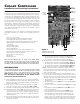
Figure 2