
- Compumotor OEM650/OEM650X OEM350/OEM350X Drive and Drive/Indexer User Guide

19
OEM650/OEM650X • INSTALLATION
OEM
s
e
r
i
e
s
REMOTE
REF
CURRENT
DUMP
VDC+
VDC-
A+
A-
B+
B-
POWER
FAULT
OEM
s
e
r
i
e
s
REMOTE
REF
CURRENT
DUMP
VDC+
VDC-
A+
A-
B+
B-
POWER
FAULT
OEM
s
e
r
i
e
s
REMOTE
REF
CURRENT
DUMP
VDC+
VDC-
A+
A-
B+
B-
POWER
FAULT
OEM
s
e
r
i
e
s
REMOTE
REF
CURRENT
DUMP
VDC+
VDC-
A+
A-
B+
B-
POWER
FAULT
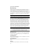
1"
2.0"
6.0"
3.0"
5.5"
Minimum
4.65"
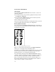
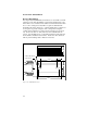
Figure 2-17. OEM650/OEM650X OEM-HS2 Minimum Area Panel Layout
Jumper Functions
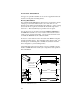
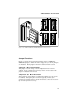
Figure 2-1 shows the location and function of the 11 OEM650/
OEM650X jumpers. When the unit is shipped to you, all 11 jumpers
are installed. Each jumper's function is defined in this section.
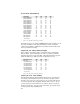
Jumper #1: Motor Current Range
This jumper sets the range of user configurable motor current
settings. Refer to Tables 2-8 and 2-9 for motor current values with
jumper 1 installed and removed.
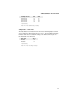
Jumpers #2 - #5: Motor Resolution
These jumpers control motor resolution (how many steps are in one
revolution). Although higher resolutions typically result in finer
positioning and improved low-speed smoothness, it does not necessar-
ily result in improved accuracy.