
- Compumotor OEM650/OEM650X OEM350/OEM350X Drive and Drive/Indexer User Guide

5
OEM650/OEM650X • INSTALLATION
WARNING
The drive and motor should be mounted to a heatsink. Drive mounting does not affect
the following tests, but if you operate the OEM650/OEM650X for extended periods
without proper mounting, it will damage the drive and/or motor. When you complete
the quick tests, remove power to the drive.
Perform installation and test procedures in a properly grounded
environment. Compumotor recommends the use of a grounding
strap.
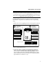
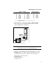
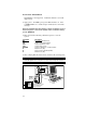
1. Remove the cover by applying pressure to the 25-pin D connector.
To remove cover,
push the 25-pin D
connector in while
holding the sides of
the unit.
1110987654321
Jumpers
A
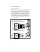
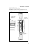
When the cover is
removed, the
jumpers will be
visible at the upper
portion of the unit.
B
Auto
Test
Auto
Standby
Motor
Waveform
Shape
Motor
Resolution
Motor
Current
Range
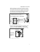
Enlarged view of jumpers
Compumotor
5500 Business Park Dr.
Rohnert Park, CA 94928
Prod: Ø571Ø2-2-6-Ø17-Ø1Ø
Made In USA
Compumotor
5500 Business Park Dr.
Rohnert Park, CA 94928
Made In USA
Prod: Ø571Ø2-2-6-Ø17-Ø1Ø
Figure 2-1. OEM650/OEM650X Jumpers
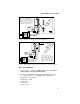
2. To test the system, you will use the Automatic Test function,
jumper 11. Remove jumper 11 to enable the function (save for
later installation). Do not remove any other jumpers. When
power is applied to the drive with jumper 11 removed, the Auto-
matic Test function will rotate the motor in an Alternating mode
approximately 6 revolutions at 1 rps.