
- Compumotor OEM650/OEM650X OEM350/OEM350X Drive and Drive/Indexer User Guide

INSTALLATION • OEM650/OEM650X
10
Quick Test: OEM650 with Separate Indexer
1. Complete steps 1- 6 from the OEM650 Quick Test, but do not
remove jumper #11 (Auto Test Function).
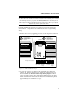
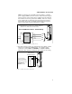
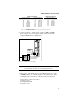
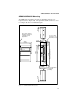
2. To connect a Compumotor indexer to the OEM650’s 25-pin D
connector refer to Figure 2-6.
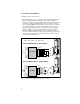
To connect a non-Compumotor indexer to the OEM650's 25-pin
D connector, refer to Figure 2-7.
3. Apply power. The OEM’s green power LED should be on. If the
red FAULT LED is on, consult Chapter 5, Troubleshooting.
This test assumes that your indexer’s motor resolution is set to
25,000 steps/rev. This is the default motor resolution setting
for the OEM650.
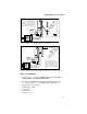
4. Using the indexer, send step pulses to the drive that will rotate the
motor one CW revolution (25,000 step pulses) at 1 rps (25,000
steps per second).
5. Using the indexer, send step pulses to the drive that will rotate the
motor one CCW revolution at 1 rps. The drive's default direction
is CCW (i.e., if the the direction input is not activated, the motor
will rotate CCW—if the direction input is activated, the motor will
rotate CW). If the motor does not rotate in the desired direction,
reverse the direction sense for your system by reversing the leads
going to the A+ and A- terminals.
WARNING
Never connect or disconnect any component to or from the drive with power
applied. System damage or personal injury may occur.
6. After verifying that the motor moves CW and CCW, turn off power.
❐ Disconnect cables and resistor.