
- Compumotor OEM650/OEM650X OEM350/OEM350X Drive and Drive/Indexer User Guide
25
OEM650/OEM650X • INSTALLATION
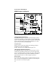
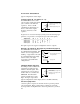
Remote Input
The Remote input is an optically isolated input that uses an ILQ2
quad OPTO isolator. The REMOTE+ terminal is connected to the
anode of the OPTO lead via a 681Ω current limiting resistor. The
REMOTE- terminal is connected to the cathode of the OPTO lead.
The OPTO requires a minimum of 3.5 mA (≈3.5VDC) to ensure proper
system operation.
This input allows you to reduce current to a motor from a remote
location. This is accomplished by changing the current select
resistor via the remote input. When the remote input is enabled, the
open collector transistor connected to the REMOTE screw terminal
will conduct to ground. If the CURRENT and REMOTE terminals are
shorted together (with a wire) motor current will be reduced to zero.
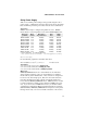
Motor current can also be reduced by a percentage if CURRENT and
REMOTE are shorted with the appropriate resistor. A remote motor
current value must be selected (see Table 2-8) to set the operating
current. Identify the current resistor associated with the operating
current you select. Use the resistor values to determine the remote
resistor that must be installed between the CURRENT and REMOTE
terminals. Use the following equation to detemine R
REMOTE
.
R
REMOTE
= -13,300 (3650 + R
C
) / (R
C
- R
S
)
R
C
= Resistor associated with the operating current
R
S
= Resistor associated with the desired standby current
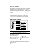
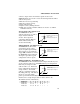
Fault Output
This output is an open-collector, open emitter output from a ILQ2
OPTO isolator. The output transistor will conduct when the drive is
functioning properly. The transistor will not conduct properly when
any of the following conditions exist.
❏ No power is applied to the drive
❏ There is insufficient voltage (<24VDC)
❏ The driver detects a motor fault
❏ The remote input is enabled
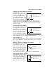
This output has the following electrical characteristics:
❏ V
CE
= 35VDC
❏ V
CESAT
= 0.3VDC
❏ Collector Current = 10 mA maximum
❏ Dissipation = 100 mW maximum