
- Compumotor OEM650/OEM650X OEM350/OEM350X Drive and Drive/Indexer User Guide

29
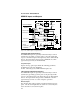
OEM650/OEM650X • INSTALLATION
connect a single-ended, incremental, optical encoder to the
OEM650X. When an encoder is used, the following functions will be
added to the system:
❏ Encoder referenced positioning
❏ Encoder position servoing
❏ Motor stall detection
❏ Higher accuracy homing function
❏ Multi-axis stop (also available without an encoder—see FSF in
command reference)
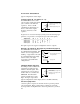
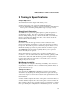
Encoder Inputs A, B, Z (Signals 17-19)
The OEM650X has three
dedicated inputs for use with a
single ended incremental
encoder. These inputs in
conjunction with the FS com-
mands will determine the
encoder functionality.
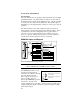
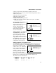
Trigger Inputs #1 - #3 (Signals 20 - 22)
The OEM650X has three dedi-
cated Trigger inputs. These
inputs are pulled up internally.
These inputs are used with the
Trigger (TR) command to control
the OEM650X's trigger function.
The figure represents a typical
configuration of these inputs.
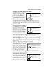
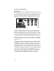
Address Signals #1 - #3 (Signals 23 - 25)
The OEM650X has three dedicated address inputs that allow you to
specify a unique address for each OEM650X in your configuration.
Units may be assigned a valid
address from 1 to 8. Each unit
in the configuration must have a
unique address. The default
address is 8 (all three inputs are
internally pulled up. The address
inputs are read only during
power-up and when Restart (Z) commands are issued. Use the
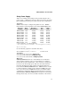
matrix below to assign unique address values. (Refer to the
# command for more information.)
Address # 87654321
Address #1 Ø 1 Ø 1 Ø 1 Ø 1
Address #2 ØØ11ØØ11
Address #3 ØØØØ1111
• Maximum low-level input: 0.8V
(Sinks 1.2 mA)
• Minimum high-level input: 2V
+5V
4.75k
HCT541
• Maximum low-level input: 0.8V
(Sinks 1.2 mA)
• Minimum high-level input: 2V
+5V
4.75k
HCT244
• Maximum low-level input: 0.8V
(Sinks 1.2 mA)
• Minimum high-level input: 2V
+5V
4.75k
HCT541