Selective Call Intercom SYSTEM INSTALLATION GUIDE 1308003 REV.B 301 Fulling Mill Road, Suite G ©Copyright 2008 by On-Q/Legrand, Middletown, PA 17057 Inc All Rights Reserved. (800)-321-2343 www.onqlegrand.
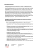
Federal Communications Commission Statement This device complies with Part 15 of the FCC Rules. Operation is subject to the following two conditions: • • This device may not cause harmful interference, and This device must accept any interference received, including interference that may cause undesired operation. This equipment has been tested and found to comply with the limits for a class B digital device, pursuant to Part 15 of the Federal Communications Commission (FCC) rules.
TABLE OF CONTENTS I. Introduction 1 A. Installation Safety Precautions 1 II. System Components Overview 2 A. System Components 2 III. Wiring Specifications 3 A. Specifications 3 B. Guidelines 3 C. Unit Placement 3 D. Termination Instructions 3 IV. System Wiring Overview 4 A. Pre-Wiring (Rough-In) 4 B. Final Wiring (Trim-Out) 7 V. System Configuration 12 A. Choosing Unit Names 12 B. Modifying Reply Options 13 C. Room Options 13 D. Door Options 14 E. Patio Options 15 F.
301 Fulling Mill Road, Suite G ©Copyright 2008 by On-Q/Legrand, Middletown, PA 17057 Inc All Rights Reserved. (800)-321-2343 www.onqlegrand.
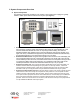
I. Installation Introduction The On-Q/Legrand Selective Call Intercom System is an advanced Cat 5 based intercom system consisting of 2-gang Room Units, Patio Units and Door Units. Each of these user stations are connected with a single Cat 5 cable to an Intercom Module in the enclosure. The Room Units contain an intuitive graphical user interface in the form of a liquid crystal display, similar to today’s cell phones.
II. System Components Overview A. System Components The following components (in addition to the 24VDC 1.25A 30 watt power supply) are typically utilized to make up the Selective Call Intercom System (see Figure 1). Figure 1 SCI Module Room Unit Patio Unit • • • • Door Unit Video Door Unit Selective Call Intercom Distribution Module/s: These modules are typically installed in the On-Q enclosure.
III. Wiring Specifications A. Specifications Minimum cable rating: Category 5e UTP, 4 pair solid conductors (24 AWG), 100 ohm, 100 Mhz, General Purpose (CM), UL listed Maximum length per run: 325 feet (except where noted in documentation) Termination standard: T568A Terminating plug type: Solid Conductor RJ45 B. Guidelines • Do not exceed 25 lbs. of force when pulling cable. • Do not splice cables. • Do not staple cables. Use wire ties with screw mounts to loosely secure cabling.
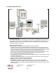
IV. System Wiring Overview Figure 4 A. Pre-Wiring (Rough-In) The rough-in of the Selective Call Intercom System should be completed during the construction phase of the home and prior to the installation of drywall. The following section will instruct you on the proper methods to pre-wire your cable and rough-in the openings for the various Selective Call Intercom System components.
• Repeat these instructions for each and every Room Unit that will be installed in the system (maximum of 32). Selective Call Patio Unit(s) The procedure to rough-in the Patio Unit(s) is as follows: • Typically the Patio Unit(s) will be installed on the exterior of the home next to a patio door. Verify the Patio Unit(s) location(s) with the homeowner or builder before proceeding.
Selective Call Door Unit(s) The procedure to rough-in the Door Unit(s) is as follows: • Typically the Door Unit(s) will be installed on the exterior of the home next to an entrance door, where you would normally find a standard doorbell. Verify the Door Unit(s) location(s) with the homeowner or builder before proceeding.
Selective Call Intercom Distribution Module/s The rough-in of the On-Q Enclosure that will house the Intercom Distribution Module/s will need to be completed per the enclosure’s installation instructions. There is no further rough-in work required for the Intercom Distribution Module since this component will mount directly in the On-Q Enclosure during trim-out. B. Final Wiring (Trim-Out) The trim-out of the system should be completed after wall coverings have been finalized.
Selective Call Patio Unit(s) The procedure to trim-out the Patio Unit(s) is as follows: • As shown in Figure 6, the first step to installing the Selective Call Patio Unit is to place the included weather proofing rear gasket against the gang or back box, and secure the gasket in place with the included mounting bracket. NOTE: Insure that the mounting bracket is installed with the center tab pointed up, as the Patio Unit will be “hung” from this tab in a later step.
Selective Call Door Unit(s) The procedure to trim-out the Door Unit(s) is as follows: NOTE: Make sure that the included weather proofing gasket is placed as shown in Figure 8. center tab rear gasket • As shown in Figure 8, the first step to installing the Selective Call Door Unit is to place the included rear gasket against the gang or back box, and secure the gasket in place with the included mounting bracket.
Selective Call Intercom Distribution Module The procedure to install the Intercom Distribution Module is as follows: • As shown in Figure 11, there is an “ADDRESS” jumper block located at the top of the rear of the Selective Call Intercom Distribution Module. This jumper block is used to select the Master module, and up to three Slave modules when cascading Distribution Modules. Each Selective Call Distribution Module is shipped with the jumper in the Master position.
ROOM1 ALL ROOM2 PATIO1 DOOR1 SETTINGS SETTINGS ROOM1 INSTALLER SETUP Reply Options Reply Options Door Options Room Options Door Options Patio Options Installer Setup DOOR PATIO OPTIONS OPTIONS Select Unit: DOOR1 Disc. Settings Room Options Firmware Info System Reset DOOR PATIO 1OPTIONS Release: ENABLE Trigger: DISABLE BACK BACK Figure 13 • Insert the Intercom Distribution Module into the mounting bracket and insert the bracket into the On-Q enclosure.
V. System Configuration The following section explains how to use any Selective Call Room Unit to configure and personalize the Selective Call System using the Settings selection from the Room Unit Main Menu (see Figure 16). Refer to the Selective Call System User Manual (P/N 1308001) shipped with the Selective Call Module to familiarize yourself with the operation of the Selective Call Intercom System. A.
Back Door Back Gate Balcony Balcony 2 Basement Door Casita Deck Dock Front Door Front Entry Front Gate Front Porch Garage Guest House Master Deck Patio Porch Side Door Veranda Table 2 B. Modifying Hands-Free Reply Options This option may be configured by the Integrator or homeowner from one Room Unit in the house. This global option affects all Room and Patio Units, and determines the amount of time a receiving unit remains in hands free reply mode.
The Theme function (see Figure 25) allows you to select one of four different color pallets for that particular Room Unit’s display (shown in Figure 26). ROOM1 ALL Figure 26 ROOM1 ALL ROOM1 ALL ROOM1 ALL ROOM2 PATIO1 DOOR1 SETTINGS ROOM2 PATIO1 DOOR1 SETTINGS ROOM2 PATIO1 DOOR1 SETTINGS ROOM2 PATIO1 DOOR1 SETTINGS Theme 1 Theme 2 Theme 3 Theme 4 D. Door Options (Local Settings) These options may be configured by the Integrator or homeowner from any Room Unit in the house.
E. Patio Options (Local Settings) These options may be configured by the Integrator or homeowner from any Room Unit in the house. The Patio Options are specific only to the selected Patio Unit. Select “Patio Options” from the Settings screen (see Figure 30) and use the talk/select and arrow buttons to select which Patio Unit you would like to configure (see Figure 31). The first setting “Status:” see Figure 32) determines whether that Patio Unit is enabled (ON) or disabled (OFF).
Door Unit Hands-Free Reply Options The Reply Options screen (see Figure 36) is used to select the amount of time all Door Units remain in hands-free reply mode. The options are 60 seconds, 30 seconds, 15 seconds, 10 seconds (the default), 5 seconds, or disabled (see Figure 37). REPLY OPTIONS Door Reply: ROOM1 INSTALLER SETUP Reply Options 10 sec Door Options Disc.
Disc. Settings The Discovery Settings option, selected from the Installer Setup screen (see Figure 42) is an option screen that allows the installer to turn ON the unit beep that occurs when units are discovered. It is turned OFF by default (see Figure 43) so as not to disturb homeowners at night if there is a temporary power outage and restoration of power. When turned ON, each unit in the system will beep as it is discovered upon power initialization. ROOM1 INSTALLER SETUP ROOM1 DISC.
Firmware Info The Firmware Info option, selected from the Installer Setup screen (see Figure 46) is an option screen that displays the Unit Name, firmware revision and address of that particular Room Unit (see Figure 47). This information may be very handy if the installer is troubleshooting a problem over the phone with On-Q Technical Support. ROOM1 INSTALLER SETUP FIRMWARE INFO Unit Name: Reply Options Door Options ROOM 4 Rev: v1.0rc2.28 Address: 90:1040 Disc.
System Default Values ROOM 1-8 DOOR 1-8 PATIO 1-8 Default Unit Names: Default Reply Options: Hands-Free Reply Room: Hands-Free Reply Patio: 10 seconds 10 seconds Default Room Options: Room Volume + / LCD Brightness: Chime Volume: Monitor: Mute: Theme: Time Out: Sort: 75% 90% 75% ON ON Theme 1 1 minute Dynamic Default Door Options: Chime #: Volume: Chime Volume: Chime #1 70% 75% Default Patio Options: Status: Volume: Chime Volume: All Call: Monitor: Time Out: ON 70% 75% NO NO 1 minute Installer Set
VI. Troubleshooting This section will detail possible solutions to common problems that might occur during installation of or in using the On-Q/Legrand Selective Call Intercom System. A. Contact Information If you are unable to locate a solution here, please access our website at www.onqlegrand.com for the latest information. You can also reach us at 1-800-321-2343. B.
C. Warranty Information LIMITED ONE YEAR PRODUCT WARRANTY On-Q/Legrand ("On-Q") warrants to the original end user ("Customer") that those products manufactured by or for On-Q ("Warranted Products"), as conclusively evidenced by the name or logo of On-Q appearing on the product, will be free from defects in workmanship and materials, under normal use, for (1) one year from the date of original purchase from On-Q or its authorized dealer or installer.
VII. Installer Checklist This checklist is provided to help the installer keep track of Unit Names and Options as part of the installation process. Global Rm/Patio Hands Free Reply: 5,10,15,30,60,dis. Room #1 New name FW rev Address Sort: D/A Mute: On/Off Mon: On/Off T/O: 1,5,10 Theme: 1,2,3,4 New name FW rev Address Sort: D/A Mute: On/Off Mon.: On/Off T/O: 1,5,10 Theme: 1,2,3,4 New name FW rev Address Sort: D/A Mute: On/Off Mon.