
Installation Manual


Page 3
301 Fulling Mill Road, Suite G ©Copyright 2008 by On-Q/Legrand,
Middletown, PA 17057 Inc All Rights Reserved.
(800)-321-2343 www.onqlegrand.com
III. Wiring Specifications
A. Specifications
Minimum cable rating: Category 5e UTP, 4 pair solid conductors (24 AWG),
100 ohm, 100 Mhz, General Purpose (CM), UL listed Maximum length per run: 325 feet (except
where noted in documentation)
Termination standard: T568A
Terminating plug type: Solid Conductor RJ45
B. Guidelines
• Do not exceed 25 lbs. of force when pulling cable.
• Do not splice cables.
• Do not staple cables. Use wire ties with screw mounts to loosely secure cabling.
• Avoid running Cat 5 cable parallel to 120V/240V AC wiring or fixtures within 12 inches.
• Avoid “ganging” any intercom unit with a lighting dimmer switch. Maintain at least 12 inches of
separation from dimmer switches.
• If you must cross AC wiring, do so at a 90 degree angle with at least 2 inches of separation.
• Maintain a minimum 1” bend radius.
• Do not untwist Cat 5 conductors more than 1/2” at any termination point.
• Keep cables away from HVAC ducts, or anything with sharp edges that could cause damage.
• Clearly label all cabling runs at both ends. Use the distance between your hand and your elbow
as a guide to determine how far from the end of the cable to place the label.
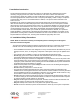
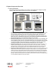
C. Unit Placement
To provide optimal display quality of the LCD on the
Selective Call Room Unit, the two gang box that it is
mounted in should be located for eye level operation.
The bottom of the two gang box should be approximately
56” from the floor see Figure 2).
Carefully plan the placement of Room Units before
rough-in to avoid any feedback issues that are
associated with audio devices.
• Avoid placing units back to back on a common wall to
minimize the likelihood of any feedback issues. If units
must be placed on both sides of a common wall, then
place insulation in the back cavity of each electrical
box.
• Do not place intercom units within the same room in
the home.
• Avoid any situations where the speaker of a unit points
to and has a clear line of sight to another unit’s
microphone.
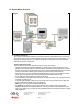
D. Termination Instructions
All components of the Selective Call Intercom System use RJ45 plugs terminated to the T568A
wiring standard shown in Figure 3.
RJ-45
Pin
1 – White/Green
2 – Green
3 – White Orange
4 – Blue
5 – White/Blue
6 – Orange
7 – White/Brown
8 – Brown
RJ-45
Pin
1 – White/Green
2 – Green
3 – White Orange
4 – Blue
5 – White/Blue
6 – Orange
7 – White/Brown
8 – Brown
Figure 2
Figure 2
Figure 3