
Users Guide User guide

DMXPathfinder LR Installation & Assembly
9
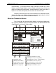
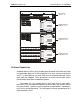
Pin 1 -- Signal Common (shield)
Pin 2 – DMX Data (-)
Pin 3 – DMX Data (+)
Pin 4 – Talkback Data (-)
Pin 5 – Talkback Data (+)
Be sure to use one twisted pair for the DMX data and the other for Talkback
data. It is also good practice to label each station cable and corresponding
terminal block header position with the cable number.
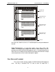
Input Modules are provided with both 5-position rear-mounted terminal blocks
and parallel 5-pin XLR male faceplate jacks. In some installations, the
hardwired cable terminates at female jacks mounted on an auxiliary panel
provided by the system supplier. In this case, no connection is made to the
Input Module’s rear terminal blocks; instead short XLR patch cables are used to
interconnect the auxiliary panel female jacks with the Input Module’s male
faceplate jacks.