
Users Guide User guide


DMXPathfinder LR Installation & Assembly
10
Patching
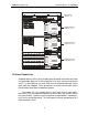
To assign outputs to inputs, first remove the front cover to access the Crosspoint
Card (E).
Each of the 32 rotary selector switches on the Crosspoint Card corresponds to
an output in this Output Module. The switch is set to the input number from one
to eight that you wish to feed this output from. Position one corresponds to input
“A” and position eight to input “H”. Positions zero and nine are unused.
0
1
2
3
4
5
6
7
8
9
0
1
2
3
4
5
6
7
8
9
0
1
2
3
4
5
6
7
8
9
0
1
2
3
4
5
6
7
8
9
0
1
2
3
4
5
6
7
8
9
0
1
2
3
4
5
6
7
8
9
0
1
2
3
4
5
6
7
8
9
0
1
2
3
4
5
6
7
8
9
0
1
2
3
4
5
6
7
8
9
0
1
2
3
4
5
6
7
8
9
0
1
2
3
4
5
6
7
8
9
0
1
2
3
4
5
6
7
8
9
0
1
2
3
4
5
6
7
8
9
0
1
2
3
4
5
6
7
8
9
0
1
2
3
4
5
6
7
8
9
0
1
2
3
4
5
6
7
8
9
ROUTER ASSIGNMENT
SW1 thru SW32
JUMPER SETTINGS
* indicates factory default setting
MODULE CONFIGURATION
Each switch sets routing for
one DMX output line. Switch
position numbers "1" thru "8"
correspond to DMX inputs "A"
thru "H". Do not use positions
"0" & "9".
Example:
To route input "D" to output 25
set SW25 to "4".
JP1/Motherboard
open = fan ON
*shorted = fan OFF
JP1/Output Card
*open = power ON
shorted = CPU power control
(used with LR version only)
A
B
CF
D
E
0
1
2
3
4
5
6
7
8
9
0
1
2
3
4
5
6
7
8
9
0
1
2
3
4
5
6
7
8
9
0
1
2
3
4
5
6
7
8
9
0
1
2
3
4
5
6
7
8
9
0
1
2
3
4
5
6
7
8
9
0
1
2
3
4
5
6
7
8
9
0
1
2
3
4
5
6
7
8
9
0
1
2
3
4
5
6
7
8
9
0
1
2
3
4
5
6
7
8
9
0
1
2
3
4
5
6
7
8
9