
Users Guide User guide


DMXPathfinder LR Index
14
carried out. Try swapping input or output cable connections on the back of the
DMXPathfinder modules with adjacent ones to use a different receiver and
transmitter circuits. Next, a DMX tester should be used to either transmit DMX
in place of the control console, or receive DMX in place of the receiving
device(s). Check the receiving device by connecting the DMX tester directly to
it in transmit mode. Then set the tester to receive mode and monitor the data
coming to the DMXPathfinder from the console, by plugging into the Input
Module faceplate XLR with a female-female cable. If this test does not point to
the data source or the receiving device as being the cause of the problem, there
may be a slight incompatibility between them as far as DMX512 is concerned.
However, if the two units had previously worked together, these tests will point to
a problem in the DMX cable installation or in one of the DMXPathfinder
modules.
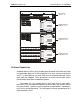
At this point, the suspect Output Module’s output card or should be
withdrawn from its chassis and the spare unit inserted in its place (remember to
power down before withdrawing or inserting any cards). If this proves that the
original unit is defective, inspect the card for signs of damage or any other
obvious cause. Return the defective card to the factory for repair unless you
have the facilities to carry out your own service. For more serious defects, such
as power supply or fan failure, disconnect the entire module and take it to the
test bench for repair, or return it to the factory. DMXPathfinder MR modules are
not difficult to service with basic tools and test equipment. If the suspect module
proves to be good, test the DMX cable installation for open or shorted lines
using a loopback test connector. You can easily make one of these from a 5-pin
male XLR plug by shorting together pins 2&4 and 3&5. Insert the plug into the
female DMX-out receptacle at the far end of the cable and apply a DMX signal
to the desired DMXPathfinder input. Switch-select that input at the crosspoint
card. If the wiring installation is good, the green & amber LEDs on the Input
Module, crosspoint card and output card will all be illuminated. Note that this
test is possible only in systems where all five XLR pins are wired.
If the above tests yield passing results and the problem persists, it may be
necessary to use the Fluke LAN Cable Meter to do a high-frequency analysis of
the suspect cable runs. This test will quickly indicate any anomalies having to
do with cable impedance and capacitance that would result in excessive signal
distortion or attenuation. This test will help to locate less-obvious problems such
as pinched or over-heated cabling that cannot be found with simple continuity
checks.