
Users Guide User guide

DMXPathfinder LR Installation & Assembly
5
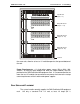
recommended). To calculate minimum height, add up the number of 2U Input
Modules and 4U Output Modules to be installed, then add at least 2U for vent
panels and allowance for power bars, connector panels or other accessories if
required. Louvered, locking front and rear doors are recommended.
Locate the rack such that at least 3 feet of clearance is allowed at the front,
2 feet at the back, and sufficient clearance at one side (preferably the left) to
permit service access to the internal cable connections.
MOUNTING TERMINATION BOARDS
One of two types of cable termination boards are normally supplied with
the system to provide the physical interface between the DMXPathfinder MR
Output Modules and external station cabling.
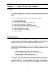
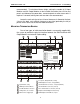
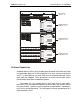
PORT APORT BPORT CPORT DPORT E
DMX INPUTS
PORT FPORT GPORT H
OUTPUT 5-8 OUTPUT 1-4
J2 J1
J4 J3
J6 J5
J10
J12
J9
J11
J13
J8 J7
OUTPUT 13-16 OUTPUT 9-12
OUTPUT 21-24 OUTPUT 17-20
OUTPUT 29-32 OUTPUT 25-28
INTER-MODULE BUS
INTER-MODULE BUS
INTER-MODULE BUS
32-WAY OUTPUT MODULE
PC-COM
CPS
TxD
CABLE B THRU
CABLE B IN
CABLE A THRU
CABLE A IN
RxD
COM
TxD+
TxD-
RxD+
RxD-
POWER IN
POWER IN
100-240V
100-240V 50/60Hz
50/60Hz
DMX Pathfinder MR
MODEL NUMBER
SERIAL NUMBER
MADE IN CANADA
100-240 VAC
50/60Hz 1.0A
1 1 1 1 1 1 1 12 2 2 2 2 2 2 23 3 3 3 3 3 3 34 4 4 4 4 4 4 45 5 5 5 5 5 5 5
Input Module, 8-way
Crosspoint / Output Module, 32-way
DMX Input Terminal Blocks
DMX Output Connectors, 4-way (DB25F)
PC Communications Connection (unused)Inter-Module Bus Connection
Inter-Module Bus Connector, 1-8 Inputs (DB37F)
Output Terminal Adapter Board, 32-way Linking Cable, 37 conductor
Mains Power Supply Input
Inter-Module Bus Connector (unused)
DMX Output Terminal Blocks, 2 piece
TB32
TB24
TB16
TB8
TB31
TB23
TB15
TB7
TB30
TB22
TB14
TB6
TB29
TB21
TB13
TB5
TB28
TB20
TB12
TB4
TB27
TB19
TB11
TB3
TB26
TB18
TB10
TB2
TB25
TB17
TB9
TB1
A
A
F
B
G
KC
H
LD
E
J
M
B G C D
J
ML
F H K
E