
Data Sheet


LA6-W18D-9_26
4. Wiring
The wiring example indicates how to connect to external contacts for every classication.
If there are any special applications that require asking questions concerning this product, feel free to contact your PATLITE Sales
Representative.
4.1. Wiring Examples
■
About the “Mode Change” switch-over
When entering the “Mode Change”, the operating mode can be changed to the “Smart Mode.” In the “Smart Mode”, various
lighting and alarm patterns can be arranged. Visit our company’s homepage (http://www.patlite.com) for further details.
* For the “Mode Change” switch-over, refer to
“5. Operating Directions”
for further details.
* When lighting and ashing are used together in the Signal Tower mode with a PLC, it is necessary to separate the ashing and
non-ashing circuit outputs on the PLC side.
* Even when starting two or more units simultaneously, a lag will occur during ashing or the Alarm sound.
1
2
3
Point
Screwless Terminal Block wiring method (Model Direct Mount/ Screwless Terminal Block)
Lever
・The minus driver blade should be at least 2.5mm by 0.4mm
in size.
・Do not forcibly push the lever more than necessary with the
driver. Failure to comply may damage the unit.
・Strip 9mm (plus or minus 1mm) of wire insulation from the
wire to insert it in the Terminal Block.
・
When removing the lead wire, do not just pull to remove.
(Be sure to operate the lever to release the lock.)
The driver is removed to
release the lever. (Check to
make sure the lead wire has
been locked in place.)
A minus driver etc. is used to pry the
lever slot of the Terminal Block open,
by pushing straight onto the lever slot.
The stripped side of the lead
wire is inserted in the slot.
TN
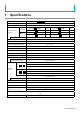
Wiring Example Index
LED Tier 1 / Input 1
/ ①
Red
Function Name
[Signal Tower] mode/[Smart Mode]
Lead Wire Color
(Cable Specication)
PIN No.
(
Direct Mount/
Screwless Terminal
Block Type
)
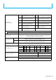
TN
Screwless Terminal Block Connector PIN Arrangement
( Direct Mount/ Screwless Terminal Block Specifications)
TN
■Recommended lead wire specifications
■Alarm Sound Pattern (Factory Default)
UL1007 / UL1430
Wire Type
Alarm 1
Alarm 2
Alarm 1 and Alarm 2 Entered Simultaneously
Alarm Sound No. 2
Alarm Sound No. 9
0.5~1.5mm
2
Wire Gauge (Solid Wire)
AWG20~16
Wire Gauge (Frayed Wire)
1
Red
2
Orange
3
Green
4
Blue
5
White
6
Gray
7
Black
8
Yellow
9
Gray
10
Black
11
Purple
LED1/Input1
LED2/Input2
LED3/Input3
LED4/Input4
LED5/Input5
Alarm 1/Input6
Alarm 2/Input7
Power Wire
Flashing
/Pulse Enable Common
Power Line
(Signal-line Side)
Mode Change
Alarm Sound No. 1
→
Refer to the "Screwless
Terminal Block connector
PIN arrangement” gure on
the right.
<Note> The lead wire color does not indicate the
LED luminescence color.
・Temperature rating should be above 75
0
C and the conductor material should
be of copper wire.