
Installation Instructions

7
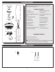
ASSEMBLY INSTRUCTIONS
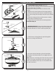
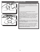
10. Use wire connectors to connect the fan wires to the
power supply wires according to the wiring diagram and
the following instructions:
• Connect the green wires from the downrod and
mounting bracket to the bare/green (ground) supply
wire.
• Connect the white wire from the fan to the white
(neutral) supply wire.
• Connect the black and blue wires from the fan to the
black (hot) supply wire.
Note: If there is a second hot/power wire coming from
the outlet box, connect it to the blue (light power) fan
wire for separate light and fan control.
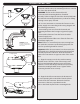
Important: After the connections have been made, the
connected wires should be turned upward and pushed
carefully up into the outlet box. Place the black and
white wire connections on opposite sides of the outlet
box.
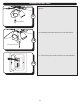
11. Align the canopy over the loosened mounting
bracket screws. Place the J-slot of the canopy onto
the loosened mounting bracket screws and rotate
clockwise. Secure the canopy with the two previously
removed mounting bracket screws. Tighten all the
mounting bracket screws securely.
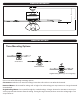
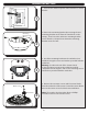
9. Lift the downrod into the mounting bracket. Rotate the
downrod until the tab in the mounting bracket is seated in
the slot in the downrod ball.
WARNING: The fan and/or downrod should
not rotate in the mounting bracket, if installed
correctly. Failure to align the slot in the downrod ball with
the tab on the mounting bracket may result in fan falling
causing serious injury or death.
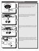
12. Align the lock-fast connector in the direction of
its corresponding hole in the blade. Place the blade
over the lock-fast connector. Rotate the lock-fast
connector so that it is perpendicular to the
hole in the blade. Repeat for the remaining blades.
Canopy
Round
Hole
Mounting
Bracket Screw
J-shaped Slot
11
Black (hot)
White (neutral)
Bare/Green
(ground)
Black
Blue
White
Green
WARNING: Do NOT
wire the fan motor to a
variable-speed (dimmer)
wall control.
10
Tab
Slot
Downrod
9
12
Blade
Blade Arm
Lock-Fast
Connector