USER MANUAL MODEL 2720/I Series NetLink-T1™ T1/Fractional T1 CSU/DSU Part# 07M2720I-UM Doc#08618U2-001, Rev. B Revised 10/26/06 Copyright © 2006 Patton Electronics Company All Rights Reserved An ISO-9001 Certified Company SALES OFFICE (301) 975-1000 TECHNICAL SUPPORT (301) 975-1007 http://www.patton.
TABLE OF CONTENTS Section Page 1.0 Warranty Information .............................................................2 1.1 Warranty Statement 1.2 Radio and TV Interference 1.3 Industry Canada Notice 1.4 FCC Compliance 1.5 Service Information 1.6 CE Notice 2.0 General Information...............................................................5 2.1 Features 2.2 General Product Description 3.0 PPP Operational Background................................................6 3.1 Applications 3.
1.3 INDUSTRY CANADA NOTICE The Canadian Department of Communications label identifies certified equipment. This certification means that the equipment meets certain telecommunications network protective, operational and safety requirements. The Department does not guarantee the equipment will operate to the user's satisfaction. Before installing this equipment, users should ensure that it is permissible to be connected to the facilities of the local telecommunications company.
2.0 GENERAL INFORMATION Thank you for your purchase of this Patton Electronics product. This product has been thoroughly inspected and tested and is warranted for One Year parts and labor. If any questions arise during installation or use of the unit, contact Patton Electronics Technical Services at (301) 975-1007. 2.
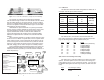
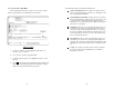
3.1.1 Switch S2 Patton 2701/I Bridge Router The table below shows the default configurations for Switch S2. A description of all S2 options follows this table. Ethernet LAN S2 SUMMARY TABLE PEC Device w/ Serial I/F Position Function Factory Default Figure 1. Cisco router with serial interface, configured as PPP Half Bridge. S2-1 Data Rate On For example, the customer site is assigned the addresses 192.168.1.0/24 through 192.168.1.1/24. The address 192.168.1.
Line Framing Options: Switch S2-6 and S2-7: Clock Mode D4/Superframe: The D4 framing format, as specified in AT&T TR62411 is the standard in which twelve frames make up a superframe. All signaling and synchronization are done inband. Extended Superframe (ESF): Extended Superframe, as specified in AT&T TR 54016, consists of twenty-four (24) T1 frames. The framing bits are now used for framing, CRC and the Facility Data Link (FDL).
3.1.2 Switch S1 Switch S1-3: Tx Clock Invert The chart below shows the default configurations for Switch S1. A description of all S1 options follows this table. S1 SUMMARY TABE Position Function Factory Default S1-1 RDL Type On S1-2 Reserved On S1-3 Tx Clock Invert Off S1-4 Line Build Out Off S1-5 Selected Option V.
4) 3.2 SOFTWARE CONFIGURATION The Model 2720 features a menu-driven command system that allows you to monitor/configure its operating parameters. Follow the instructions below to configure the Model 2720 using the software selections: 1) Plug the 9-pin male end of the cable to your terminal or computer’s DB-9 serial port and start up the terminal emulator software if necessary. Plug the miniature stereo plug into the rear of the unit.
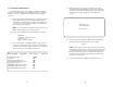
3.2.1 Introduction to Main Menu After entering the password, you may access all of the system’s functions and parameters. The Main Menu looks like this: HELPFUL HINTS 1. To make a selection, key the highlighted letter that corresponds to a menu selection. 2. To execute the selection, type [Enter/CR] 3. To toggle between options on a highlighted selection, Press [space]. 4. Select d Save Changes from Main Menu after making modifications to any Model 2720 parameter.
3.2.2 System Configuration The default System Configuration menu looks like this: ESF: This stands for Extended Superframe Format, a line format developed by AT&T. AT&T Technical Reference 54016 (TR 54016) defines the ESF, a format which is commonly used to allow monitoring of the network interface performance over the Facility Data Link (FDL). AT&T TR 62411 says, “the Extended Superframe Format “extends” the DS1 superframe structure from 12 to 24 frames…for a total of 4632 bits.
B8ZS: Bipolar violations occur when consecutive pulses are of the same polarity. In B8ZS, or Bipolar Eight Zero Substitution, bipolar violations are introduced deliberately to indicate that eight zeros have been transmitted. This special encoding is recognized by the receiver and decoded correctly. See AT&T TR62411 Section 4.2.2 for a detailed description of B8ZS. This enables information to be sent over a T1 connection without any constraints on the data’s pulse density.
f ESF Data Link: ANSI T1.403 (default) h Options: ANSI T1.403, AT&T TR54016 ANSI T1.403: This ANSI developed standard (see ANSI T1.4031995: Network-to-Customer Installation—DS1 Metallic Interface) uses the FDL to send and receive one second Performance Report Messages (PRMs). The messages contain the NI performance over the last four seconds. Thus, up to three consecutive messages may be lost without loss of information. It is available only with ESF. When ANSI T1.
unit. This will cause the unit to enter a special mode. Then turn off the unit and change the switch settings to the desired settings. When you turn the unit on again, the unit will be set up with the selected switch settings. n 3.2.3 System Diagnostics The System Diagnostics/Statistics screen looks like this: DS0 Channel Configuration Menu: [ Bandwidth/# Channels = 1,536/24 ] (default) The DS0 Channel Configuration Menu has a sub-menu that looks like this: NOTE: This screen is updated once per second.
b Remote Loop Idle (default) The Model 2720 receiving a RL can be in one of the following states: The Remote Digital Loopback (RDL) test checks the performance of both the local and remote Model 2720s, as well as the communication link between them. Data from the local DTE is sent across the entire communication circuit and looped back to the local DTE. RxPr The Model 2720 is receiving a preparatory pattern. Sack The Model 2720, upon receiving a preparatory pattern, sends an acknowledgement message.
NI STATUS The Network interface (NI) status is shown in the middle of the Diagnostics/Statistics screen. The brackets are empty when the link is operating normally. In this example, various two or three-letter messages are displayed within the brackets, illustrating what you may see if the Model 2720 is not connected at all or is in a loss of signal condition. Here are the eight status messages. Excessive zeros [EXZ], i.e., lack of pulses, detected.
Rx PRM 3.3.6 Unit Information The NetLink-T1™ transmits ANSI performance report messages once a second when the framing mode is ESF. When the ESF Data Link is set to ANSI T1.403, the unit recognizes PRMs with addresses of 38h or 3Ah. The address 3Ah indicates the PRM is coming from a Carrier, whereas the address 38h indicates the PRM is coming from a Customer. When the ESF Data Link is set to AT&T TR54016, the unit recognizes Carrier-originated PRMs, which have an address of 3Ah.
4.0 INSTALLATION Loop Timeout The Loop Timeout setting can be set to one of the following: 00:05 = 00:10 = 00:15 = 00:30 = 00:45 = 01:00 = 01:30 = 02:00 = 03:00 = NEVER = five minutes ten minutes fifteen minutes thirty minutes (default setting) forty-five minutes one hour 90 minutes two hours three hours forever—the unit will remain in loopback without user intervention. The Model 2720 is equipped with DTE, network, and power interfaces. This section briefly describes connection to each. 4.
5.0 OPERATION Once the NetLink-T1™ is installed and configured properly it is ready to place into operation. This section describes the function of the LED indicators, and the use of the loopback and pattern test modes. ER The error LED indicates various error conditions, including framing bit errors, excessive zeros, controlled slips, severe errors, or bit errors (when sending V.52 test patterns). When sending a test pattern, the LED will remain lit if the unit does not receive the identical pattern.
To perform an RDL test, follow these steps: 5.2 LOOP (V.54 & TELCO) DIAGNOSTICS 1. The NetLink-T1™ offers three V.54 loop diagnostics and is compatible with two Telco loop diagnostics. Use these diagnostics to test the CSU/DSU and any communication links. These tests can be activated via the software control port (See Section 3.2.3 System Diagnostics), via signals on the serial port interface or the front panel switch. Activate RDL. This may be done in three ways: a.
APPENDIX A 5.3 BIT ERROR RATE (V.52) DIAGNOSTICS PATTON NETLINK-T1 MODEL 2720 The NetLink-T1™ offers three V.52 Bit Error Rate (BER) test patterns. These test patterns may be invoked along with the LAL and RDL tests to evaluate the unit(s) and the communication links. When a 511, 2047, or QRSS test is invoked, the NetLink-T1™ 20 generates a pseudo-random bit pattern of 511 bits, 2047 bits or 2 bits, respectively, using a mathematical polynomial.
APPENDIX C APPENDIX B PATTON NETLINK-T1™ MODEL 2720 CABLE RECOMMENDATIONS The Patton Model 2720 Series has been performance tested by Patton technicians using twisted-pair cable with the following characteristics: PATTON NETLINK-T1™ MODEL 2720 FACTORY REPLACEMENT PARTS AND ACCESSORIES Patton Model # Description 10 - 09F............................6 Foot Control Port Cable, 25mm to DB9F 07M2720..........................User Manual Wire Gauge Capacitance Resistance 2720/C/VI.........................
APPENDIX D APPENDIX D (continued) PATTON NETLINK-T1™ MODEL 2720 PATTON ELECTRONICS MODEL 2720 INTERFACE PIN ASSIGNMENT INTERFACE PIN ASSIGNMENT M/34 Connector, Terminal Interface RJ-48C T1 (DS0) Network Interface (Female Modular Jack) Pin # 1 2 4 5 Signal RX Data (TIP 1) RX Data (RING1) TX Data (TIP) TX Data (RING) TRS Jack (RS-232 Control Port) Pin # Tx Data Rx Data Sleeve Signal Source From Model 2720 To Model 2720 N/A RS-232 Control Port (Signals at DB-25 Connector) Pin# 3 2 7 Signal Receive Tra
APPENDIX E APPENDIX E PATTON NETLINK-T1™ MODEL 2720 (continued) EIA-530 INTERFACE PIN ASSIGNMENT PATTON ELECTRONICS MODEL 2720 INTERFACE PIN ASSIGNMENT DB-25 Female Connector, Terminal Interface Pin # X.