Motherboard User’s Guide This publication, including photographs, illustrations and software, is under the protection of international copyright laws, with all rights reserved. Neither this manual, nor any of the material contained herein, may be reproduced without the express written consent of the manufacturer. The information in this document is subject to change without notice.
Motherboard User’s Guide Table of Contents Trademark ................................................................................... I Static Electricity Precautions ............................................................ III Pre-Installation Inspection ................................................................ III Features & Checklist Translations ........................................ V Chapter 1: Introduction ............................................................ 1 Key Features .
Motherboard User’s Guide Static Electricity Precautions Static electricity could damage components on this motherboard. Take the following precautions while unpacking this motherboard and installing it in a system. 1. Don’t take this motherboard and components out of their original static-proof package until you are ready to install them. 2. While installing, please wear a grounded wrist strap if possible.
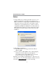
Motherboard User’s Guide Notice: 1. Owing to Microsoft’s certifying schedule is various to every supplier, we might have some drivers not certified yet by Microsoft. Therefore, it might happen under Windows XP that a dialogue box (shown as below) pop out warning you this software has not passed Windows Logo testing to verify its compatibility with Windows XP. Please rest assured that our RD department has already tested and verified these drivers.
Motherboard User’s Guide Traduction des Caractéristiques & Liste de contrôle Liste de contrôle Le coffret de votre carte mère contient les éléments suivants: • La carte mère • Le Manuel utilisateur • Un câble plat pour lecteur de disquette (optionnel) • Une câble plat pour lecteur IDE • CD de support de logiciels Caractéristiques Type de CPU • Prend en charge le CPU VIA C3 interne • Supporte le Bus Frontal de 133 MHz Chipset Ce chipset comporte VIA CLE266 Northbridge et 8235 Southbridge conformément à une a
Motherboard User’s Guide Canaux IDE internes • Deux Connecteurs IDE • Prend en Charge les modes PIO (Entrée/Sortie Programmable) et DMA (Accès Direct à la Mémoire) • Supporte maîtrise de bus Ultra DMA IDE avec vitesse de transfert de 133/100/ 66/33 Mo/sec VGA Interne • L’Accélérateur Graphique/Vidéo intégré prend en charge l’Architecture de Mémoire Partagée (SMA) optimisée • Chemins de données 128 bits séparés entre North Bridge et noyau graphique pour flux de données de pixels et accès de texture/commande
Motherboard User’s Guide d’Hôtes UHCI pour signalisation pleine/faible vitesse et un noyau de Contrôleur d’Hôtes EHCI pour signalisation haute vitesse • Le hub racine consiste en 4 ports de face en aval avec émetteurs-récepteurs de couche physique intégrés partagés par le Contrôleur d’Hôte UHCI et EHCI • Support des Spécifications d’Interface de Gestion d’Alimentation de Bus PCI version 1.1 • Support hérité pour tous les ports face à l’aval.
Motherboard User’s Guide Checkliste Funktionen & Checkliste Die Verpackung Ihres Motherboards enthält folgende Teile: • Motherboard • Handbuch • Bandkabel für Floppylaufwerke (optional) • Bandkabel für IDE-Laufwerke • Software -CD Ausstattung CPU-Typ • Unterstützt Onboard-VIA C3 CPU • Unterstützt 133 MHz Front-Side Bus Chipsatz Dieser Chipsatz besteht aus einer VIA CLE266 Northbridge und einer 8235 Southbridge.
Motherboard User’s Guide Onboard IDE-Kanäle • Zwei IDE-Header • Unterstützt die Modi PIO (Programmable Input/Output) und DMA (Direct Memory Access) • Unterstützung für IDE Ultra DMA-Busmastering mit Transferraten von 133/ 100/66/33 MB/Sek Onboard- VGA • Integrierte Grafikfunktion/Videobeschleuniger unterstützt optimierte “Shared Memory Architecture” (SMA) • Separate 128-Bit-Datenpfade zwischen der Northbridge und dem Grafikkern für Pixel-Datenfluss und extur/Befehlszugriff • Grafik-Engine auf bis zu 133MHz
Motherboard User’s Guide igkeit sowie einem EHCI Host Controller-Kern für Hochgeschwindigkeits- Signalübertragung • Root Hub besteht aus 4 Downstream-Ports mit integrierten Physical LayerÜberträgern für gemeinsame Nutzung durch UHCI und EHCI Host Controller • Unterstützt PCI-Bus Power Management Interface , Spezifikation Release 1.1 • Legacy-Unterstützung für alle Downstream-Ports Hinwei: Bestimmte Hardwarespezifikationen und Teile der softwareausstattung können ohne weitere Ankündigung abgeändert werden.
Motherboard User’s Guide Lista Traduzione Funzioni e Lista L’imballo della scheda madre é composto da: • La scheda madre • Il manuale • Una piattina per il collegamento dei drive (opzionale) • Una piattina IDE • Il CD con il Software di supporto Caratteristiche Tipo CPU • Supporta la CPU VIA C3 installata • Supporta Front Side Bus (FSB) di 133 MHz Chipset In accordo ad una archittettura scabile e innovative sono presenti nel chipset il Northbridge VIA CLE266 e Southbridge 8235.
Motherboard User’s Guide Canali IDE Integrati • Due connettori IDE • Supporto della modalità PIO (Programmable Input/Output) e DMA (Direct Memory Access) • Supporto per le modalità Bus Mastering e Ultra DMA ATA 133/100/66/33 VGA Integrato • Grafica integrata/acceleratore video supportano SMA (Shared Memory Architecture) ottimizzata • Separa i percorsi dati da 128 bit tra north bridge e graphic core per flusso di dati pixel e trama/accesso comandi • Orologio Graphics engine sino a 133MHz separato dalla memor
Motherboard User’s Guide • Il porto hub di base consiste di 4 porte downstream con ricetrasmittenti integrati nel layer fisico condivisi dalla scheda di controllo interfaccia UHCI e EHCI • Support PCI-Bus Power Management Interface Specification release 1.1 • Supporto per interfaccia risparmio energia bus PCI specifiche release 1.1 • Supporto per tutte le porte downstream precedenti Nota: Alcune specifiche hardware ed elementi software sono soggetti a variazioni senza preavviso.
Motherboard User’s Guide Traducción de Características & Lista LISTA DE VERIFICACIÓN El paquete de su placa principal contiene los sigtes.
Motherboard User’s Guide Canales IDE abordo • Dos conectores IDE • Soporta modos PIO (Entrada/Salida Programable/Programmable Input/ Output) y modos DMA (Acceso de Memoria Directo/Direct Memory Access).
Motherboard User’s Guide • Root hub consiste de 4 puertos que miran hacia abajo con transceptores de capa física integrado compartido por Controlador Anfitrión UHCI y EHCI transceivers shared by UHCI and EHCI Host Controller • Soporta Especificación de Interfaz de Administración de Energía de BUS PCI versión 1.1 • Soporte de legado para todos los puetos que miran hacia abajo Nota: Algunas especificaciones de hardware e ítems de software son sujetos a cambio sin aviso previo .
Motherboard User’s Guide Tradução da Lista & Características Lista de verificação A embalagem da sua placa principal contém os seguintes itens: • A placa principal • O Manual do Utilizador • Um cabo para a unidade de disquetes (opcional) • Um cabo para a unidade IDE • CD de suporte para o software Características Tipo CPU • Suporta CPU VIA C3 integrada • Suporta Barramento Frontal/Lateral 133 MHz Chipset Conta com VIA CLE266 Northbridge e 8235 Southbridge neste chipset, de acordo com uma arquitectura inova
Motherboard User’s Guide Canais IDE na placa • Dois conectores IDE • Suporta modos PIO (Input/Output Programável) e DMA (Direct Memory Access) • Suporta IDE Ultra DMA bus mastering com razão de transferência de 133/ 100/66/33 MB/seg VGA Integrado • Acelerador Gráfico / Vídeo suporta Arquitectura de Memória Compartida (SMA) optimizada • Caminhos de dados de 128-bit separados entre a ponte norte e o núcleo gráfico para fluxo de dados pixel e acesso textura/comando • Relógios do motor gráfico de até 133MHz des
Motherboard User’s Guide Host Controller para sinalização de velocidade total/baixa em um núcleo de Controlador EHCI Host para sinalização de alta velocidade • O núcleo de raiz consiste em 4 portas de protecção a jusante com transreceptores de camadas físicas integrados partilhados pelos controladores Host UHCI e EHCI • Suporte de gestão de energia PCI-Bus Revisão 1.
Motherboard User’s Guide 功能和检查单翻译 检查单 您的主板包装含有以下项目: • 主板 • 用户手册 • 一根磁盘驱动器扁平电缆(可选) • 一根 IDE 驱动器扁平电缆 • 软件支持 CD 功能 CPU 类型 • 支持集成 VIA C3 CPU • 支持 133 MHz 前端总线 芯片组 芯片组包含 VIA CLE266 北桥和 8235 南桥,它基于一种新型的、可扩展的架构, 能提供已经证明的可靠性和高性能。 • 高性能 CPU 接口: 支持 VIA C3 处理器;133/100/66 MHz CPU 前端总线 (FSB) • 高带宽 266MB/sec 8-bit-Link 主控器,支持 66MHz V-Link 主控接口,总带宽 可达 266MB/sec • 增强高性能 DDR/SDR DRAM 控制器,支持与主 CPU (133/100 MHz) 的 DRAM 接口同步用于灵活配置; 4 个内存插槽,最大可支持 2 GB DRAM • 集成图形/视频加速器:16/32 使用系统内存的帧缓冲;内部 AGP 4x 性能 • 并发 PCI 总线控制器:工作频率 33 MHz,符
Motherboard User’s Guide Onboard IDE 通道 • 2 个 IDE 接口 • 支持 PIO (程控输入/输出) 和 DMA (直接存储器存取) 模式 • 支持 IDE Ultra DMA 总线控制,传输速率可达 133/100/66/33 MB/sec 集成 VGA • 集成图形/视频加速器,支持优化共享内存架构 (SMA) • 北桥和图形核心间的独立 128 位数据路径,用于像素数据流和纹理/指令访问 • 由存储器时钟分离出的、最高 133 MHz 的图形引擎时钟 • 高质量 DVD 视频播放 AC’97 编解码器 • • • • • • 6 声道,符合 Intel AC’97 (REV. 2.
Motherboard User’s Guide xxii
Motherboard User’s Guide Chapter 1 Introduction This motherboard has a VIA C3 CPU onboard with front-side bus speed up to 133MHz. This motherboard integrates the VIA CLE266 Northbridge and 8235 Southbridge chipsets that support DDR 266MHz, Ultra DMA 33/66/100/133 function and remarkably high system performance under all types of system operations It supports built-in USB 2.0 providing higher bandwidth. It implements Universal Serial Bus Specification Revision 2.0 and is compliant with UHCI 1.1 and EHCI 1.
Motherboard User’s Guide Key Features The key features of this motherboard include: CPU Type • Supports the VIA C3 CPU onboard • Supports 133 MHz Front-Side Bus Chipset There are VIA CLE266 Northbridge and 8235 Southbridge in this chipset in accordance with an innovative and scalable architecture with proven reliability and performance.
Chapter 1: Introduction • Universal Serial Bus Controller: USB v2.0 and Enhanced Host Controller Interface (EHCI) v1.0 compatible; USB v1.1 and Universal Host Controller Interface (UHCI) v1.1 compatible Memory Support • Two 184-pin DIMM sockets for DDR memory modules • Supports DDR266/200 memory bus • Maximum installed memory is 2GB Expansion Slots • One CNR slot • Two 32-bit PCI slots for PCI 2.
Motherboard User’s Guide • Advanced power management and power saving capabili• • • • ties. Stereo Line-in function shared with Surround out. High quality pseudo-differential analog CD Audio input. S/PDIF Output support: Output 96 / 48 kHz with 24 / 20 /16 bits Valuable add-on software technology: Support most industry standards of PC 3D sound and unique karaoke function support featured with microphone echo, key shifting, and vocal cancellation.
Chapter 1: Introduction • Compliant with Universal Host Controller Interface Specification Revision 1.1 • PCI multi-function device consists of two UHCI Host Controller cores for full-/low-speed signaling and one EHCI Host Controller core for high-speed signaling • Root hub consists 4 downstream facing ports with integrated physical layer transceivers shared by UHCI and EHCI Host Controller, up to six functional ports • Support PCI-Bus Power Management Interface Specification release 1.
Motherboard User’s Guide Package Contents Your motherboard package ships with the following items: • • • • • The motherboard The User Guide One diskette drive ribbon cable (optional) One IDE drive ribbon cable The Software support CD Optional Accessories You can purchase the following optional accessories for this mainboard. • The Extended USB module • The CNR v.
Chapter 2: Motherboard Installation Chapter 2 Motherboard Installation To install this motherboard in a system, please follow these instructions in this chapter: • • • • • • Identify the motherboard components Install a CPU Install one or more system memory modules Make sure all jumpers and switches are set correctly Install this motherboard in a system chassis (case) Connect any extension brackets or cables to connectors/ headers on the motherboard • Install peripheral devices and make the appropriate co
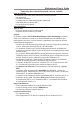
Motherboard User’s Guide Motherboard Components CPU_FAN1 DIMM IDE1 IO PORTS J5 USB1 IDE2 ATX1 AUDIO2 CD1 PCI SPK1 JBAT1 FDC1 CNR1 LABEL DIMM1/2 IDE1/2 ATX1 USB1 FDC1 PANEL1 SYSTEM_FAN1 JBAT1 SPK1 PCI 1-2 CD1 SYSTEM_FAN1 PANEL1 COMPONENTS Two 184-pin DDR SDRAM sockets Primary/Secondary IDE connectors Standard 20-Pin ATX Power connector Front Panel USB header Floppy Disk Drive connector Front Panel Switch/LED header System Fan connector Clear CMOS jumper Speaker header 32-bit PCI slots Analog Audio
Chapter 2: Motherboard Installation LABEL AUDIO2 J5 CPU_FAN1 CNR1 COMPONENTS Front Panel Audio header USB Card Reader header CPU Fan connector Communications Networking Riser slot I/O Ports The illustration below shows a side view of the built-in I/O ports on the motherboard. Shared with J5 PS/2 Mouse (Optional) Use the upper PS/2 port to connect a PS/2 pointing device. Use the lower PS/2 port to connect a PS/2 PS/2 Keyboard keyboard.
Motherboard User’s Guide Installing Memory Modules This motherboard accommodates two 184-pin 2.5V DIMM sockets (Dual Inline Memory Module) for unbuffered DDR266/ 200 memory modules (Double Data Rate SDRAM), and maximum 2.0GB installed memory. DDR SDRAM is a type of SDRAM that supports data transfers on both edges of each clock cycle (the rising and falling edges), effectively doubling the memory chip’s data throughput. DDR DIMMs can synchronously work with 200 MHz or 266 MHz memory bus, providing 1.
Chapter 2: Motherboard Installation 2. Align the memory module with the socket. There is a notch on the DIMM socket that you can install the DIMM module in the correct direction. Match the cutout on the DIMM module with the notch on the DIMM socket. 3. Install the DIMM module into the socket and press it firmly down until it is seated correctly. The socket latches are levered upwards and latch on to the edges of the DIMM. 4. Install any remaining DIMM modules.
Motherboard User’s Guide Jumper Settings Connecting two pins with a jumper cap is SHORT; removing a jumper cap from these pins, OPEN. 1 JBAT1 JBAT1: Clear CMOS Jumper Use this jumper to clear the contents of the CMOS memory. You may need to clear the CMOS memory if the settings in the Setup Utility are incorrect and prevent your mainboard from operating. To clear the CMOS memory, disconnect all the power cables from the motherboard and then move the jumper cap into the CLEAR setting for a few seconds.
Chapter 2: Motherboard Installation Install the Motherboard Install the motherboard in a system chassis (case). The board is a FLEX ATX size motherboard. You can install this motherboard in an ATX case. Make sure your case has an I/O cover plate matching the ports on this motherboard. Install the motherboard in a case. Follow the case manufacturer’s instructions to use the hardware and internal mounting points on the chassis.
Motherboard User’s Guide Here is a list of the PANEL1 pin assignments. Pin Signal Pin Signal 1 HD_LED_P(+) 2 FP PWR/SLP(+) 3 HD_LED_N(-) 4 FP PWR/SLP(-) 5 RESET_SW_N(-) 6 POWER_SW_P(+) 7 RESET_SW_P(+) 8 POWER_SW_N(-) 9 RSVD_DNU 10 KEY Connecting Optional Devices Refer to the following for information on connecting the motherboard’s optional devices: 1 J5 USB1 1 AUDIO2 SPK1 1 1 SPK1: Speaker Header Connect the cable from the PC speaker to the SPK1 header on the motherboard.
Chapter 2: Motherboard Installation AUDIO2: Front Panel Audio Header This connector allows the user to install auxiliary front-oriented microphone and line-out ports for easier access. Pin Signal Pin Signal 1 AUD_MIC 2 AUD_GND 3 AUD_MIC_BIAS 4 AUD_VCC 5 AUD_FPOUT_R 6 AUD_RET_R 7 HP_ON 8 KEY 9 AUD_FPOUT_L 10 AUD_RET_L USB1: Front panel USB Header The motherboard has USB ports installed on the rear edge I/O port array. Additionally, some computer cases have USB ports at the front of the case.
Motherboard User’s Guide J5: USB Card Reader Header (optional) This connector is for connecting internal USB card reader. You can use a card reader to read or transfer files and digital images to your computer. Pin 1 3 5 Signal Pin Signal VCC5 2 USBUSB+ 4 GND KEY Note1: The J5 is shared with the lower USB port located beside the VGA port of the I/O back panel. Please see “I/O Ports” for more information. Note2: Please check the pin assignment of the cable and the USB connector on the motherboard.
Chapter 2: Motherboard Installation Install Other Devices Install and connect any other devices in the system following the steps below. IDE1 1 IDE2 1 1 FDC1 Floppy Disk Drive The motherboard ships with a floppy disk drive cable that can support one or two drives. Drives can be 3.5" or 5.25" wide, with capacities of 360K, 720K, 1.2MB, 1.44MB, or 2.88MB. Install your drives and connect power from the system power supply.
Motherboard User’s Guide The motherboard ships with an IDE cable that can support one or two IDE devices. If you connect two devices to a single cable, you must configure one of the drives as Master and one of the drives as Slave. The documentation of the IDE device will tell you how to configure the device as a Master or Slave device. The Master device connects to the end of the cable. Install the device(s) and connect power from the system power supply.
Chapter 2: Motherboard Installation When you first start up your system, the BIOS should automatically detect your CD-ROM/DVD drive. If it doesn’t, enter the Setup Utility and configure the CD-ROM/DVD drive that you have installed. On the motherboard, locate the 4-pin header CD1. Pin 1 2 3 4 Signal CD IN L GND GND CD IN R Expansion Slots This motherboard has one CNR and two 32-bit PCI slots. PCI1 PCI2 CNR1 Follow the steps below to install a CNR/PCI expansion card. 1. 2.
Motherboard User’s Guide 3. 4. Install the edge connector of the expansion card into the slot. Ensure the edge connector is correctly seated in the slot. Secure the metal bracket of the card to the system chassis with a screw. CNR Slot You can install the CNR (Communications and Networking Riser) cards in this slot, including LAN, Modem, and Audio functions. PCI Slots You can install the 32-bit PCI interface expansion cards in the slots.
Chapter 3: BIOS Setup Utility Chapter 3 BIOS Setup Utility Introduction The BIOS Setup Utility records settings and information of your computer, such as date and time, the type of hardware installed, and various configuration settings. Your computer applies the information to initialize all the components when booting up and basic functions of coordination between system components. If the Setup Utility configuration is incorrect, it may cause the system to malfunction.
Motherboard User’s Guide Running the Setup Utility Every time you start your computer, a message appears on the screen before the operating system loading that prompts you to “Hit if you want to run SETUP”. Whenever you see this message, press the Delete key, and the Main menu page of the Setup Utility appears on your monitor. AMIBIOS SIMPLE SETUP UTILITY – VERSION 1.21.12 (C) 2000 American Megatrends, Inc.
Chapter 3: BIOS Setup Utility Standard CMOS Setup Page This page displays a table of items defining basic information about your system. AMIBIOS SETUP – Standard CMOS Setup (C) 2000 American Megatrends, Inc. All Rights Reserved Date (mm/dd/yy) : Thu Apr 15, 2004 Time (hh/mm/ss) :16:46:44 LBA Blk PIO Type Size Cyln Head WPcom Sec Mode Mode Mode Pri Master: Auto Pri Slave: Auto Sec Master:Auto Sec Slave: Auto Floppy Drive A: 1.
Motherboard User’s Guide Advanced Setup Page This page sets up more advanced information about your system. Handle this page with caution. Any changes can affect the operation of your computer. AMIBIOS SETUP – Advanced Setup (C) 2000 American Megatrends, Inc. All Rights Reserved Quick Boot Enabled 1st Boot Device IDE-0 Floppy 2nd Boot Device 3rd Boot Device CD/DVD-0 Try Other Boot Devices Yes S.M.A.R.T.
Chapter 3: BIOS Setup Utility S.M.A.R.T. for Hard Disks Enable this item if any IDE hard disks support the S.M.A.R.T. (Self-Monitoring, Analysis and Reporting Technology) feature. BootUp Num-Lock This item determines if the Num Lock key is active or inactive at system start-up time. Floppy Drive Swap If you have two diskette drives installed and you enable this item, drive A becomes drive B and drive B becomes drive A.
Motherboard User’s Guide DDR Timing by SPD This item enables or disables the DDR timing defined by the Serial Presence Detect electrical. DDR CAS# Latency This item determines the operation of DDR memory CAS (column address strobe). It is recommended that you leave this item at the default value. The 2T setting requires faster memory that specifically supports this mode. DRAM Bank Interleave Enable this item to increase DDR memory speed.
Chapter 3: BIOS Setup Utility Power Management Setup Page This page sets some parameters for system power management operation. AMIBIOS SETUP – Power Management Setup (C) 2000 American Megatrends, Inc.
Motherboard User’s Guide LAN/Ring Power On The system can be turned off with a software command. If you enable this item, the system can automatically resume if there is an incoming call on the Modem/Ring, or traffic on the network adapter. You must use an ATX power supply in order to use this feature. Keyboard Power On If you enable this item, system can automatically resume by pressing any keys, hot or typing in the password. You must use an ATX power supply in order to use this feature.
Chapter 3: BIOS Setup Utility PCI / Plug and Play Setup Page This page sets up some parameters for devices installed on the PCI bus and those utilizing the system plug and play capability. AMIBIOS SETUP – PCI / PLUG AND PLAY SETUP (C) 2000 American Megatrends, Inc.
Motherboard User’s Guide Load Optimal Settings If you select this item and press Enter a dialog box appears. If you press Y, and then Enter, the Setup Utility loads a set of failsafe default values. These default values are not very demanding and they should allow your system to function with most kinds of hardware and memory chips. Note: It is highly recommended that users enter this option to load optimal values for accessing the best performance.
Chapter 3: BIOS Setup Utility OnBoard FDC Use this item to enable or disable the onboard floppy disk drive interface. OnBoard Serial PortA Use this item to enable or disable the onboard COM1 serial port, and to assign a port address. Onboard Parallel Port This item enables or disables the onboard LPT1 parallel port, and assigns a port address. The Auto setting will detect and available address. Parallel Port Mode Use this item to set the parallel port mode.
Motherboard User’s Guide USB Controller Enable this item to select the USB ports or disable. USB Function for DOS Enable this item if you plan to use the USB ports on this motherboard in a DOS environment. ThumbDrive Support for DOS Enable this item to make a small portion of memory storage device for the USB ports. CPU PnP Setup Page This page helps you manually configure the mainboard for the CPU.
Chapter 3: BIOS Setup Utility Hardware Monitor Page This page sets up some parameters for the hardware monitoring function of this mainboard. AMIBIOS (C) 2000 American *** System Hardware *** CPU Vcore Vcc2.5V +3.3V +5 V +12V VBAT CPU Fan1 SYSTEM Fan1 CPU Temperature SYSTEM Temperature SETUP – Hardware Monitor Megatrends, Inc. All Rights Reserved 1.632 V 2.496 V 3.392 V 4.945 V 12.032V 3.
Motherboard User’s Guide Change Password If you highlight this item and press Enter, a dialog box appears that you can enter a Supervisor password. You can enter no more than six letters or numbers. Press Enter after you have typed in the password. There will be the second dialog box asking you to retype the password for confirmation. Press Enter after you have retyped it correctly.
Chapter 4: Software & Applications Chapter 4 Software & Applications Introduction This chapter describes the contents of the support CD-ROM that comes with the motherboard package. The support CD-ROM contains all useful software, necessary drivers and utility programs to properly run our products. More program information is available in a README file, located in the same directory as the software. To run the support CD, simply insert the CD into your CD-ROM drive.
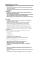
Motherboard User’s Guide Installing Support Software 1 2 3 Insert the support CD-ROM disc in the CD-ROM drive. When you insert the CD-ROM disc in the system CDROM drive, the CD automatically displays an Auto Setup screen. The screen displays three buttons of Setup, Browse CD and Exit on the right side, and three others Setup, Application and ReadMe at the bottom. Please see the following illustration. The Setup button runs the software auto-installing program as explained in next section.
Chapter 4: Software & Applications Auto-Installing under Windows 2000/XP If you are under Windows 2000/XP, please click the Setup button to run the software auto-installing program while the Auto Setup screen pops out after inserting the support CD-ROM: 1 The installation program loads and displays the following screen. Click the Next button. 2 Select the items that you want to setup by clicking on it (the default options are recommended). Click the Next button to proceed.
Motherboard User’s Guide Installing under Windows NT or Manual Installation If you are under Windows NT, the auto-installing program doesn’t work out; or you have to do the manual installation, please follow this procedure while the Auto Setup screen pops out after inserting the support CD-ROM: 1 2 3 Click the ReadMe to bring up a screen, and then click the Install Path at the bottom of the screen. Find out your mainboard model name and click on it to obtain its correct driver directory.