
Installation Guide
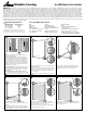

A: Slide first bracket into slot on post and position
at desired height.
B: Drill two 3/16" holes through each bracket and
post, 1" from each end of bracket. C: Fasten each
bracket to post with two #12x1" flat head screws
(not provided).
Cut remaining boards to required length.
A: Slide one spacer into each post, followed by a
bracket.
B: Position a board into the brackets and fasten
using four #8x3/4" pan head screws (not provided).
Repeat until there is one board left to install.
Slide final spacer and bracket into each post.
A: Drill two 3/16" holes through each bracket and
post, 1" from each end of bracket.
B: Fasten brackets to posts with two #12x1" flat
head screws (not provided).
A: Position board into brackets and fasten using
four #8x3/4" pan head screws (not provided).
B: Install post caps.
1
4 5 6
2 3
II37_MF_Install Guide_V2_LTR
Modular Fencing
Installation Instructions
Cut board to required length. Slide board into
brackets and fasten board to brackets with four
#8x3/4" pan head screws (not provided).
Ensure holes on edge of bracket are on desired side.
Tools and Materials NeededImportant Information
Drill
Driver bits
Hammer
Hammer drill
5/16" Drill bit for concrete
3/16" Drill bit for metal
7/16" Wrench
Level
Measuring tape
Wood fence boards
Brackets for Wood Boards
Posts
#12x1" flat head screws
#8x3/4" pan head screws
Post hole digger
Shovel
Concrete mixing equipment
Concrete trowel
Dry premixed concrete (per post):
Climate with frost heave - 200lb.*
Climate without frost heave - 100lb.*
*Quantities are estimated. Always check with
your local codes for post hole size and depth.
Maximum Post
Spacing
6 ft
4 ft
Maximum Wind
Gust Speed*
Up to 105 mph
Up to 125 mph
*Wind speeds per ASCE 7-16, Exposure Category B,
Risk Category 1, installed on flat ground. For all other
applications consult with a local professional engineer.
No representation or warranty is given that your particular application of these products complies with relevant building codes. Therefore consult with professionals
and local building officials before beginning work: (i) to ensure compliance with relevant building codes for your application; (ii) to identify appropriate safety gear that is to be used
during installation such as a safety harness when working above ground; (iii) to ensure that the work area is free from utilities, services and hazards; and, (iv) to clarify any instructions
or warnings that may not be clear. It is the responsibility of the installer to evaluate the conditions and determine the appropriate hardware and procedure. Failure to do so could
result in personal injury, damage to the product, or other damage. Work in a safe manner wearing protective gear such as gloves, eyewear, headwear, footwear and clothing. When
using tools always comply with operation manuals and instructions. Metal and other materials may have sharp edges and could fragment or splinter during or as a result of handling
or cutting. Do not use these products in connection with any substance that is or may be harmful or corrosive to the products. Inspect and maintain these products on a regular basis.
No member of The Peak Group of Companies (as defined at www.peakproducts.com) shall be liable for any loss or damage resulting from the improper installation or use of this product. In
the unlikely event that any member of The Peak Group of Companies becomes liable for any loss or damage, the aggregate liability shall be limited to the retail purchase price of the product.
Peak® products and the materials associated therewith are protected by patents, designs, copyright and/or trademarks. All trademarks are used under license from Peak Innovations
Inc. May be subject to patent(s) or patent(s) pending.
Always check your local codes for post hole size and
depth. Post holes should extend below the frost line.
Measure and mark the position of all posts and
ensure they are aligned.
A: For hard-surface posts: Position first post. For
concrete attachment, use hammer drill with 5/16"
masonry bit to drill four holes 3" deep through each
corner of post base. Clean holes. Use hammer to
insert assembled concrete anchors (provided) until
washer is touching post base. Use 7/16" wrench to
tighten nuts. Ensure post is plumb. Position second
post (do not secure it yet).
B: For in-ground posts: Position first post and second
post. Dig the post holes. Position posts in the post
holes and brace plumb. Mix and pour concrete into
the post holes.
Recommended post depth underground: 17½"
level
17½"
A A A
B
B B B
C
A
A B