224-EN WIRELESS CONTROLLER INSTALLATION & INTERFACE GUIDE USING AS REPLACEMENT CONTROLLER Confirm software version on existing controllers See Parameter 80 If Parameter 80 is 18 or lower change Parameter 54 to 1 ® THE PEELLE COMPANY FREIGHT DOORS I CAR GATES I CAR ENCLOSURES TECHNICAL SUPPORT 1-800-787-5020 ext 275 Guide No.
Contents 1.0 SAFETY WARNING 2.0 LANDING DOOR CONTROLLER INSTALLATION 3.0 4.0 5.0 1 2 2.1 LANDING DOOR CONTROLLER MOUNTING 2 2.2 LANDING DOOR WIRING LAYOUT - STANDARD OPERATORS 3 2.3 LANDING DOOR WIRING LAYOUT - EXTRA HIGH TORQUE OPERATORS 4 2.4 LANDING DOOR POWER CONNECTIONS 5 2.5 LANDING DOOR ENCODER 6 2.6 LANDING DOOR OPERATORS - STANDARD OPERATORS 7 2.7 LANDING DOOR OPERATORS - EXTRA HIGH TORQUE 8 2.8 LANDING DOOR EMERGENCY UNLOCKING DEVICE (EUD) 9 2.
6.0 CONTROLLER SETTINGS 6.1 7.0 26 DOOR MOTION PROFILES AND PARAMETERS 26 TROUBLESHOOTING 29 7.1 INDEPENDENT MODE 29 7.2 AUTOMATIC MODE 30 7.3 ELEVATOR INTERFACE OPERATION 31 7.4 ERROR CODES 32 7.5 LANDING DOOR LCD 33 7.6 CAR DOOR LCD 34 8.0 TECHNICAL SPECIFICATIONS 35 9.0 FCC/ISED DECLARATION 36 10.0 EC DECLARATION OF CONFORMITY ® THE PEELLE COMPANY FREIGHT DOORS I CAR GATES I CAR ENCLOSURES TECHNICAL SUPPORT 1-800-787-5020 ext 275 37 Guide No.
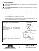
1.0 SAFETY WARNING Electrical Hazard Warning Symbol – Failure to observe this warning could result in electrical shock or electrocution. ! Operational Hazard Warning Symbol – Failure to observe this warning could result in dangerous or unsafe conditions. Installation Note: This product should be installed and serviced by a qualified elevator technician familiar with its operation and hazards involved.
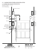
2.0 LANDING DOOR CONTROLLER INSTALLATION 2.1 LANDING DOOR CONTROLLER MOUNTING Mount the Landing door Controller to the hoistway wall. Use 1/4” inch hardware. Alternate Location Lowest Landing Recommended location Operator SLA Controller locations (where provided) 4 Feet Encoder Floors above lowest landing Recommended locations Alternate Location Interlock ® THE PEELLE COMPANY FREIGHT DOORS I CAR GATES I CAR ENCLOSURES TECHNICAL SUPPORT 1-800-787-5020 ext 275 2 Guide No.
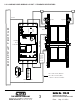
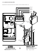
2.2 LANDING DOOR WIRING LAYOUT - STANDARD OPERATORS Power Operator Interlock Encoder Landing Door Controller DI & ZONE H O I S T WAY T R O U G H Operator DC Landing Door Junction Box or Trough Door lock contact (DI) and Door Close Contact (DC) connect to elevator controller EUD Hall Pushbuttons ® THE PEELLE COMPANY FREIGHT DOORS I CAR GATES I CAR ENCLOSURES TECHNICAL SUPPORT 1-800-787-5020 ext 275 3 Guide No.
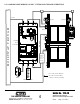
2.3 LANDING DOOR WIRING LAYOUT - EXTRA HIGH TORQUE OPERATORS Power Operator Interlock Encoder Landing Door Controller SLA Controller DI & ZONE H O I S T WAY T R O U G H Operator DC Landing Door Junction Box or Trough Door lock contact (DI) and Door Close Contact (DC) connect to elevator controller EUD Hall Pushbuttons ® THE PEELLE COMPANY FREIGHT DOORS I CAR GATES I CAR ENCLOSURES TECHNICAL SUPPORT 1-800-787-5020 ext 275 4 Guide No.
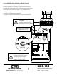
2.4 LANDING DOOR POWER CONNECTIONS Connect controllers in accordance with local electrical codes. Power branch circuit should come from machine room disconnect 10 amp circuit for each line of doors. Use #14AWG [2mm] copper wire for power connection. 1 Ø Power 208-240V AC 5.5A, 50/60 Hz • ON/OFF switch disconnects both lines • If neutral is not used, main disconnect must break both lines.
2.5 LANDING DOOR ENCODER Install and wire encoder same side as the controller. Do not extend the encoder wire. Shield White Yellow Green Brown GND COMM B A 12V ENCODER Landing Door Encoder Landing Door Controller Landing Door Encoder ® THE PEELLE COMPANY FREIGHT DOORS I CAR GATES I CAR ENCLOSURES TECHNICAL SUPPORT 1-800-787-5020 ext 275 6 Guide No.
2.6 LANDING DOOR OPERATORS - STANDARD OPERATORS Wire both door motors in parallel. Use #18AWG [1mm] wire in conduit for motor connection. Do not combine motor wires with control wires in same conduit. Note: Low speed winding is not used. Cap black wires separately (R4-R5). Landing Door Operator Landing Door Controller T1 T1 R2 R2 R3 R3 3 2 Landing Door Operator 1 MOTOR ® THE PEELLE COMPANY FREIGHT DOORS I CAR GATES I CAR ENCLOSURES TECHNICAL SUPPORT 1-800-787-5020 ext 275 7 Guide No.
2.7 LANDING DOOR OPERATORS - EXTRA HIGH TORQUE Use #18AWG [1mm] wire in conduit for motor connection. Do not combine motor wires with control wires in same conduit. Connect CAN and COMM wires between controllers. Notes 1. Low speed winding is not used. Cap black wires separately (R4-R5) 2.
2.8 LANDING DOOR EMERGENCY UNLOCKING DEVICE (EUD) The Emergency Unlocking Device is located on the landing side and contains a toggle switch which must be wired to the controller. NOTE: Only in jurisdictions not requiring unlocking devices, a jumper needs to but added in lieu of the EUD switch.
2.9 LANDING DOOR ZONE SWITCH (ZNS) The landing door Zone Switch located in top of interlock box activates the controller for the Landing door at which the elevator car is located.
2.10 LANDING DOOR HALL PUSHBUTTONS HALL DOOR OPEN BUTTON (HDO) 1 Where provided, wire landing station door OPEN pushbuttons as shown. When elevator car is within landing ZONE, pushbutton inputs will be transmitted to the Car Door controller for connection to elevator control. HALL DOOR CLOSE BUTTON (HDC) 2 Where provided, wire landing station door CLOSE pushbutton as shown.
2.11 LANDING DOOR LIGHT CURTAIN (OPTIONAL) Install and wire Landing Door Light Curtain where provided. Note: V+ to RE contact must close when beams are blocked To landing box or trough Light Curtain Controller Power 8 RE V+ Landing Door Controller See job specific wiring schematic Landing Door Landing Door Light Curtain ® THE PEELLE COMPANY FREIGHT DOORS I CAR GATES I CAR ENCLOSURES TECHNICAL SUPPORT 1-800-787-5020 ext 275 12 Guide No.
3.0 CAR DOOR (GATE) CONTROLLER INSTALLATION 3.1 CAR DOOR LOCATION AND WIRING LAYOUT Mount the Car Door Controller to the car door rail spreader. Mount to same side as the Encoder. Use 1/4” Hardware. Spreader Car Door Motor Encoder Car Door Controller Car Door Buzzer Reversing Edge Car Top Junction Box ® THE PEELLE COMPANY FREIGHT DOORS I CAR GATES I CAR ENCLOSURES TECHNICAL SUPPORT 1-800-787-5020 ext 275 13 Retiring Cam Motor Guide No.
3.2 CAR DOOR POWER CONNECTIONS Connect controllers in accordance with local electrical codes. Power branch circuit should come from machine room disconnect 10 amp circuit for each line of doors. Use #14AWG [2mm] copper wire for power connection. 1 Ø Power 208-240V AC 5.5A, 50/60 Hz • ON/OFF switch disconnects both lines • If neutral is not used, main disconnect must break both lines.
3.3 CAR DOOR ENCODER Install and wire encoder. Do not extend the encoder wire. Shield White Yellow Green Brown GND COMM B A 12V ENCODER Car Door Controller Car Door Encoder ® THE PEELLE COMPANY FREIGHT DOORS I CAR GATES I CAR ENCLOSURES TECHNICAL SUPPORT 1-800-787-5020 ext 275 15 Guide No.
3.4 CAR DOOR (GATE) OPERATOR Use #18AWG [1mm] wire in conduit for motor connection. Do not combine motor wires with control wires in same conduit. Note: Low speed winding is not used. Cap black wires separately (T8-T9). Car Door Operator 1 T1 Car Door Controller 2 T6 3 T7 On large car doors where provided wire opposite car door operator in parallel. ® THE PEELLE COMPANY FREIGHT DOORS I CAR GATES I CAR ENCLOSURES TECHNICAL SUPPORT 1-800-787-5020 ext 275 16 Guide No.
3.5 RETIRING CAM MOTOR Use #18AWG [lmm] wire in conduit for motor connection. Do not combine motor wires with control wires in same conduit. Attention! 220 Volt 3 Ø Retiring Cam Motors Only Attention! For 110 Volt 1 Ø Retiring Cam Motors for battery lowering see elevator control panel Retiring Cam Motor Y1 Y2 Y3 4 Car Door Controller 5 6 Where provided on wide landing doors, wire opposite side retiring cam motor in parallel.
3.6 CAR DOOR REVERSING EDGE (OPTIONAL) Wire reversing edge as shown where provided. 8 RE V+ Car Door Controller Car Door Panel Reversing Edge ® THE PEELLE COMPANY FREIGHT DOORS I CAR GATES I CAR ENCLOSURES TECHNICAL SUPPORT 1-800-787-5020 ext 275 18 Guide No.
3.7 WARNING BUZZER - + BUZZER Install and wire door close warning buzzer as shown. See parameter 94 for constant or pulsing tone. RED BLACK Car Door Controller BUZZER Attention! Warning Buzzer is mounted in Auxiliary strobe controller (27465) if strobe light is provided ® THE PEELLE COMPANY FREIGHT DOORS I CAR GATES I CAR ENCLOSURES TECHNICAL SUPPORT 1-800-787-5020 ext 275 19 Guide No.
4.0 COMMISSIONING 4.1 CAR DOOR Make sure all Landing Doors and Car Doors are adjusted and run freely by hand in the door guides without binding or sticking. 1. Turn power ON IND AUTO OPEN CLOSE _ + RET CAM ENTER 2. Set AUTO<>IND switch to IND 3. Using the OPEN, CLOSE and RETCAM cam buttons, ensure the car door operator(s) and retiring cam motor(s) are phased for correct rotation. If a motor rotates in the wrong direction, switch any two of the three motor wires 4.
4.2 LANDING DOOR • Ensure Landing Door interlock is mechanically unlocked. Ideally car is level at floor with retiring cam extended • Ensure all EUD switches are set to the SET position 1. Turn power ON IND AUTO 2. Set AUTO<>IND switch to IND 3. Using the OPEN and CLOSE buttons, ensure the landing door operators are phased for correct rotation. If a motor rotates in the wrong direction, switch any two of the three motor wires. OPEN CLOSE _ + ENTER 4.
4.3 LANDING AND CAR DOOR OPERATION AND TESTING With elevator control inputs removed, test the following Sequence of Operation using the OPEN, CLOSE and RETCAM buttons. OPEN CLOSE RET CAM 1. Remove elevator control inputs to DO, DC, SE, DCM 2. Make sure the controllers are set to AUTO 3. Use the OPEN, CLOSE and RETCAM buttons to test the door and car door and retiring cam sequence of operation. IND AUTO _ + ENTER 4.
5.0 ELEVATOR CONTROLLER INTERFACE 5.1 ELEVATOR TO DOOR CONTROLLER INPUT CONNECTIONS Control Interface Inputs to the car door controller are the only interface to the elevator control for door operation. Note: front and rear inputs are completely separate. INPUT COM Add jumper to the INPUT COM from V- when car car door controller V+ is used for the input voltage. Note: where elevator control voltage is used, connect INPUT COM to elevator controller according to elevator control prints. Do not use V+ or V-.
5.2 ELEVATOR TO DOOR CONTROLLER OUTPUT CONNECTIONS HALL OPEN - output relay Contact closes when zoned hall door open button is pressed. REVERSING EDGE - output relay Output - normally open contact closes and normally closed contact opens when edge is activated. HALL CLOSE - output relay Contact closes when zoned hall door close button is pressed. DOOR STOP - output relay Normally open contact closes and normally closed contact opens, when zoned hall door stop button is pressed or doors are stuck.
5.3 LANDING AND CAR DOOR INTERLOCKING CIRCUITS Wiring Note: The following interlock safety circuit wiring is for reference only. REFER TO THE ELEVATOR PRINTS FOR PROPER INTERLOCK WIRING. Elevator Control Operation 1) All DC (hoistway door closed) and GC (car gate closed) contacts should be connected in series and that the contacts be made when the doors and gates are closed. 2) All DI (hoistway door lock) contacts should be connected in series and the contacts be made when all doors are locked.
6.0 CONTROLLER SETTINGS 6.
Parameter Description 50 52 53 Control Interface: set discrete or CAN bus interface 00 = discrete, 01 = CAN Car Door Designation: 00 = Front, 01 = Rear (only displayed if Parameter 50 = 01) CmcMedia: 00 = RF, 01 = Wired RS_485 Range Landing Pre Set Car Pre Set 00-01 N/A 00 00-01 N/A 00 00-01 00 00 00-01 00 00 04-18 10 10 55 USING AS REPLACEMENT CONTROLLER If Parameter 80 is 18 or lower change Parameter 54 to 01 Lost Communication Reaction Time 04 = 0.4 sec 05 = 0.5 sec . 60 . 18 = 1.
Parameter Description Range Landing Pre Set Car Pre Set 85 USER 2 options 00 = USER 2 POSITION 01 = USER 1 POSITION 02 = ZONE 03 = BUZZ / STROBE 04 = DOOR OPEN POSITION 05 = DOOR CLOSED POSITION 06 = AUX2 INPUT 07 = LCT (BRIDGE MODE ONLY P50=1) 08 = OVERLOAD 09 = OVERDUTY 10 = OVERLOAD / OVERDUTY 00-06 03 00 86 Retiring Cam Startup Torque 50-99 N/A 50 00-01 N/A 00 00-01 N/A 00 00-01 01 N/A P87 88 89 93 SIMULTANEOUS OPERATION (INPUT 4 HIGH) 00 = CLOSE DIRECTION ONLY 01 = OPEN AND CL
7.0 TROUBLESHOOTING 7.
7.2 AUTOMATIC MODE PEELLE ONLY OPERATION - USED FOR COMBINED LANDING AND CAR DOOR OPERATION (AUTO-IND slider switch set to AUTO) Problem Possible Cause Action AUTO-IND slider not set to AUTO No operation from OPEN/CLOSE pushbutton Set AUTO-IND slider to AUTO All controllers must be set to AUTO.
7.3 ELEVATOR INTERFACE OPERATION Problem Possible Cause Action Are LCD input icons on Car Door controller? If not check the folowing: If Peelle power is used to power Peelle inputs, missing jumper from Input Com terminal to V– Add jumper from Input Com to V-. terminal on Car Door controller Ensure external power reference is wired to If external power is used to power Peelle inputs, Input Com.
7.4 ERROR CODES If the setting is flashing from encoder count (5 digits) to and error code (4 digits) refer to the following. How to read Example: Car Door Error 06 10 The first two digits are the sum of the first four possible errors. 06 = 02 (car door motor run error) + 04 (car motor over duty) The last two digits are the sum of the last four possible errors.
7.
7.
8.0 TECHNICAL SPECIFICATIONS Technical Data Input Power Supply Voltage Output Power Output Motor Digital Inputs Encoder Input Relay Outputs Input Indicators Output Indicators Enclosure Protection Temperature Dimensions Mounting Method Equipment Class Wireless Network Wireless Frequency Wireless Output Wireless Range User Interface Visual Display Parameters Learn Adjustment Landing Door Address Car or Landing Door Type Fail Safe Condition 3.
9.0 FCC/ISED DECLARATION FCC STATEMENT Wireless Radio FCC ID: 2AYO9-WFDCRFIF Equipment Class: Digital Transmission System Notes: 802.15.4 Transceiver Module This device complies with part 15 of FCC rules. Operation is subject to the following two conditions: (1) the device may not cause harmful interference, and (2) the device must accept any interference received, including interference that may cause undesired operation.
10.0 EC DECLARATION OF CONFORMITY Manufacturer: The Peelle Company Ltd. 195 Sandalwood Pkwy W. Brampton, Ontario L7A 1J6 CANADA We, The Peelle Company Limited of Brampton, Ontario, declare that the product designated below complies with the relevant fundamental requirements of Article 3 of the Lifts directive 2014/33/EU insofar as the product is used as intended and the following standards applied: Product: Wireless Freight Door Controller, 2.4GHz, 802.15.
® THE PEELLE COMPANY FREIGHT DOORS I CAR GATES I CAR ENCLOSURES TECHNICAL SUPPORT 1-800-787-5020 ext 275 38 Guide No.