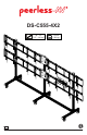
DS-C555-4X2 46" - 55" (117 - 140 cm) MAX 800 lb (363 kg) ENG 1 2014-06-20 #:009-9085-9 (2019-09-04)
WARNING ENG - Do not begin to install product until you have read and understood the instructions and warnings contained in this user guide. Always use an assistant or mechanical lifting equipment to safely lift and position equipment. This product must be installed onto flat, hard, level surface to prevent tipping. Use with heavier displays may result in instability causing tip over resulting in death or serious injury.
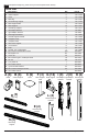
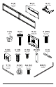
ENG Parts (Before beginning, make sure you have all parts shown below).
O (4 ) M (1 ) dual cross support P (6 ) cord bracket T (84) M8 square nut Y (1 ) 5mm allen wrench computer cover Q (6 ) R (2 ) knob U (36) cover clip Z (32) nylon shoulder washer bracket, 4x2 configuration V (18) M5 x 10mm W (28) bar nut AA (32) S (200) M8 x 16mm X (1 ) 1/4" power bit BB (1) M6 x 12mm 4 N (1 ) computer shelf 4mm allen wrench 2014-06-20 #:009-9085-9 (2019-09-04)
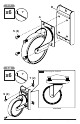
1-1 B x6 Y A S (4) 1-2 x6 ENG Do not fully tighten hardware Y T (2) S (2) SIDE VIEW 5 2014-06-20 #:009-9085-9 (2019-09-04)
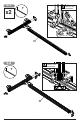
2 x3 Y T (4) T (4) D S (4) F T (4) S (4) 6 F 2014-06-20 #:009-9085-9 (2019-09-04)
3 Y x3 D TIGHTEN CONNECTING HARDWARE ENG Flush edges ENG Casters must be flush to end of horizontal leg support.
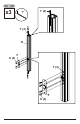
5-1 x2 TIGHTEN CONNECTING HARDWARE Y H 5-2 TIGHTEN CONNECTING HARDWARE Y H 8 2014-06-20 #:009-9085-9 (2019-09-04)
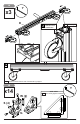
6 ENG LOCK WHEELS TIGHTEN CONNECTING HARDWARE Y E (2) 7 x4 T (4) 1/8" (3mm) 1/8" (3mm) S (6) Y L 9 2014-06-20 #:009-9085-9 (2019-09-04)
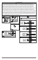
a 8 ENG Use metric formula below and diagram to the right to determine hole pattern required for center vertical support bracket. b All dimensions are metric.
9 DIS R (2) PL AY H EIG HT L (4) 10 Y TIGHTEN CONNECTING HARDWARE O (2) 11 2014-06-20 #:009-9085-9 (2019-09-04)
11 TIGHTEN CONNECTING HARDWARE Y O (2) 12 T (4) Y K (2) S (2) S (4) K T (2) 12 2014-06-20 #:009-9085-9 (2019-09-04)
P (6) Q (6) TIGHTEN CONNECTING HARDWARE P ENG Optional: Unlock wheels to move cart to desired location; Lock wheels before hanging screens.
-1 X x8 I ENG Center adaptor brackets vertically on back of screen.
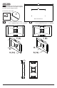
-1 "LOCKED" POSITION ENG Must hang displays on bottom row first; Secure pin in "locked" position. 15-2 "LOCKED" POSITION ENG Must hang displays on top row last; Secure pin in "locked" position.
15-3 BB ENG Optional: Insert M5 x 10mm type-F socket pin screws (V) to lock latches.
16 ENG Display adjustment IN OUT SIDE SIDE TILT BACKWARD TILT RIGHT SIDE TILT LEFT TOP SIDE UP TILT FORWARD TOP DOWN ROTATE LEFT 17 2014-06-20 ROTATE RIGHT #:009-9085-9 (2019-09-04)
17-1 N 18 2014-06-20 #:009-9085-9 (2019-09-04)
17-2 BB 1/8" (3mm) N V (2) 17-3 BB M TIGHTEN CONNECTING HARDWARE N 19 2014-06-20 #:009-9085-9 (2019-09-04)
U (36) 18 C (9) 20 2014-06-20 #:009-9085-9 (2019-09-04)
19 ENG Route cables through cord brackets.
20-1 ENG Display removal ENG Pull down on bracket cords and hold. ENG Swing screen away from cart and lift to remove. 20-2 ENG Remove displays from top row first.
20-3 ENG Remove displays from bottom row last.
LIMITED FIVE-YEAR WARRANTY Peerless Industries, Inc. (“Peerless-AV”) warrants to original end-users that each Peerless-AV® mounting product will be free from defects in material and workmanship, under normal use, for the applicable warranty period (from date of the original installation of the product). At its option, Peerless-AV will repair or replace, or refund the purchase price of, any product which fails to conform with this warranty.