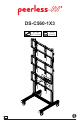
DS-C560-1X3 46" - 60" (117 - 152 cm) MAX 375 lb (170 kg) ENG 1 2015-06-30 #:009-9119-6 (2019-09-04)
WARNING ENG - Do not begin to install product until you have read and understood the instructions and warnings contained in this user guide. Always use an assistant or mechanical lifting equipment to safely lift and position equipment. This product must be installed onto flat, hard, level surface to prevent tipping. Use with heavier displays may result in instability causing tip over resulting in death or serious injury.
ENG This page intentionally left blank.
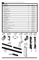
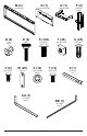
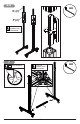
ENG Parts (Before beginning, make sure you have all parts shown below).
M (3 ) N (1 ) Q (4 ) cord bracket V (8 ) M5 x 10mm O (1 ) computer cover cross support R (4 ) knob W (20) bar nut S (120) M8 x 16mm X (12) extension adaptor T (40) U (24) M8 square nut Y (12) nylon shoulder washer P (2 ) computer shelf cover clip Z (1 ) 1/4" power bit M6 x 12mm AA (1) 5mm allen wrench BB (1) 4mm allen wrench 5 2015-06-30 #:009-9119-6 (2019-09-04)
1-1 x4 AA B A S (4) 1-2 x4 ENG Do not fully tighten hardware AA T (2) S (2) SIDE VIEW 6 2015-06-30 #:009-9119-6 (2019-09-04)
2 x2 AA T (4) T (4) H D S (4) T (4) D S (4) 7 2015-06-30 #:009-9119-6 (2019-09-04)
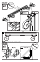
3 x2 AA H TIGHTEN CONNECTING HARDWARE ENG Flush edges ENG Casters must be flush to end of horizontal leg support.
5 TIGHTEN CONNECTING HARDWARE AA x2 J 6-1 x2 AA ENG Do not fully tighten hardware S (4) P W (2) 9 2015-06-30 #:009-9119-6 (2019-09-04)
6-2 AA K (2) P (2) TIGHTEN CONNECTING HARDWARE 7 ENG LOCK WHEELS AA TIGHTEN CONNECTING HARDWARE I 10 2015-06-30 #:009-9119-6 (2019-09-04)
8-1 S (6) x6 1/8" (3mm) 1/8" (3mm) T (4) AA L 8-2 AA TIGHTEN CONNECTING HARDWARE L (6) DIS DIS PL PL AY H AY H EIG EIG HT HT 11 2015-06-30 #:009-9119-6 (2019-09-04)
9 U (24) C (6) 12 2015-06-30 #:009-9119-6 (2019-09-04)
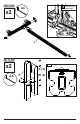
10 TIGHTEN CONNECTING HARDWARE AA M (3) ENG Tighten.
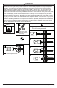
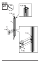
11-1 X x3 F ENG Center adaptor brackets vertically on back of screen.
12-1 "LOCKED" POSITION ENG Must hang displays on bottom row first; Secure pin in "locked" position. 12-2 BB ENG Optional: Insert M5 x 10mm type-F socket pin screws (V) to lock latches.
13 ENG Display adjustment IN OUT SIDE SIDE TILT BACKWARD TILT RIGHT SIDE TILT LEFT TOP SIDE UP TILT FORWARD TOP DOWN ROTATE LEFT 16 2015-06-30 ROTATE RIGHT #:009-9119-6 (2019-09-04)
14 Q (4) R (4) TIGHTEN CONNECTING HARDWARE Q R ENG Optional: Unlock wheels to move cart to desired location; Lock wheels before hanging screens.
15-1 O 18 2015-06-30 #:009-9119-6 (2019-09-04)
15-2 BB 1/8" (3mm) O V (2) 15-3 N BB TIGHTEN CONNECTING HARDWARE O 19 2015-06-30 #:009-9119-6 (2019-09-04)
16 ENG Route cables through cord brackets.
17 ENG Display removal ENG Pull down on bracket cords and hold. ENG Swing screen away from cart and lift to remove. 18 "UNLOCKED" POSITION ENG Remove displays from top row first.
19-1 "UNLOCKED" POSITION 19-2 "UNLOCKED" POSITION ENG Repeat step 16 to remove displays from middle row second. ENG Repeat step 16 to remove displays from bottom row last.
LIMITED FIVE-YEAR WARRANTY Peerless Industries, Inc. (“Peerless-AV”) warrants to original end-users that each Peerless-AV® mounting product will be free from defects in material and workmanship, under normal use, for the applicable warranty period (from date of the original installation of the product). At its option, Peerless-AV will repair or replace, or refund the purchase price of, any product which fails to conform with this warranty.
Peerless-AV 2300 White Oak Circle Aurora, IL 60502 Email: tech@peerlessmounts.com Ph: (800) 865-2112 Fax: (800) 359-6500 www.peerless-av.com Peerless-AV Europe Unit 3 Watford Interchange, Colonial Way, Watford, Herts, WD24 4WP, United Kingdom Customer Care 44 (0) 1923 200 100 www.peerless-av.com Peerless-AV de Mexico Ave de las Industrias 413 Parque Industrial Escobedo Escobedo N.L Mexico 66062 Servicio al Cliente 01-800-849-65-77 www.peerless-av.com © 2019, Peerless Industries, Inc.