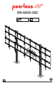
DS-S555-3X2 46" - 55" (117 - 140 cm) MAX 600 lb (272 kg) ENG 1 2014-07-28 #:009-9088-1
This page intentionally left blank.
WARNING ENG - This product is designed to be installed on solid concrete. Hardware is included for solid concrete installation. Before installing make sure the supporting surface will support the combined load of the equipment and hardware. Screws must be tightly secured. Do not overtighten screws or damage can occur and product may fail. Never exceed the Maximum Load Capacity. Always use an assistant or mechanical lifting equipment to safely lift and position equipment.
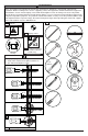
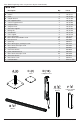
Parts (Before beginning, make sure you have all parts shown below).
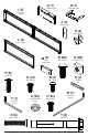
G (1) H (1) computer cover I (2) computer shelf dual cross support J (4 ) locking tab K (4) cord bracket L (2) cross support (4) M plate N (68) O (28) M8 x 16mm M8 square nut connections P (8 ) cover clip Q (14) R (4) S (1 ) M5 x 10mm M5 x 12mm 1/4" power bit W (1) T (1) 5mm allen wrench U (24) V (24) nylon shoulder washer M6 x 12mm X (8) 4mm allen wrench Y (8 ) rawl bolt M6 x 35mm 5 2014-07-28 #:009-9088-1
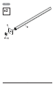
1 x2 A B W (4) 6 2014-07-28 #:009-9088-1
2 Repeat for each vertical support bracket (x4).
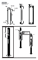
3-1 3-2 P (8) C x2 K R J TIGHTEN CONNECTING HARDWARE J K R TOP VIEW 8 2014-07-28 #:009-9088-1
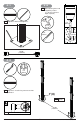
4-1 4 4-2 ENG Drill mounting holes into supporting surface (3" (76 mm) minimum depth required). ENG Align base. Mark mounting holes. 3/8" (10mm) 3" (76mm) 3/8" (10mm) 55.00" (1397mm) 4-3 3/8" (10mm) ENG Align base. Install using concrete anchors provided. Y (8) ENG Tighten. 55.00" (1397mm) ENG Maximum 35 ft • lb (47 N.M.).
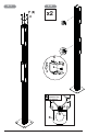
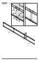
5 Repeat for each cross support assembly (x2).
6-1 Must install bottom row first. TIGHTEN HARDWARE (X2) TIGHTEN HARDWARE (X2) Cross supports must center on columns.
6-2 Must install top row last. TIGHTEN HARDWARE (X2) TIGHTEN HARDWARE (X2) Cross supports must center on columns.
7 E N (2) O (2) 13 2014-07-28 #:009-9088-1
8 Center adaptor brackets vertically on back of screen. X .98" (25mm) 7.87" (200mm) 3.94" (100mm) 2.50" (63mm) 15.75" (400mm) X 2.50" (63mm) 0.
9-1 Must hang displays to bottom row first; Secure pin in "locked" position. "LOCKED" POSITION 9-2 Must hang displays on top row second; Secure pin in "locked" position. "LOCKED" POSITION 9-3 OPTIONAL: Insert M5 x 10mm type-F socket pin screws to lock latches.
Display Adjustment IN OUT SIDE SIDE TILT BACKWARD TILT RIGHT TOP SIDE UP TILT FORWARD SIDE TILT LEFT TOP DOWN ROTATE LEFT 16 ROTATE RIGHT 2014-07-28 #:009-9088-1
10 H 11 1/8" (3mm) H G Q (2) TIGHTEN CONNECTING HARDWARE H 17 2014-07-28 #:009-9088-1
12 Route cables through cord brackets.
LIMITED FIVE-YEAR WARRANTY Peerless Industries, Inc. (“Peerless”) warrants to original end-users of Peerless® products will be free from defects in material and workmanship, under normal use, for a period of five years from the date of purchase by the original end-user (but in no case longer than six years after the date of the product's manufacture). At its option, Peerless will repair or replace, or refund the purchase price of, any product which fails to conform with this warranty.
Peerless-AV 2300 White Oak Circle Aurora, IL 60502 Email: tech@peerlessmounts.com Ph: (800) 865-2112 Fax: (800) 359-6500 www.peerless-av.com Peerless-AV Europe Unit 3 Watford Interchange, Colonial Way, Watford, Herts, WD24 4WP, United Kingdom Customer Care 44 (0) 1923 200 100 www.peerless-av.com Peerless-AV de Mexico Ave de las Industrias 413 Parque Industrial Escobedo Escobedo N.L Mexico 66050 Servicio al Cliente 01-800-849-65-77 www.peerless-av.com © 2014, Peerless Industries, Inc.