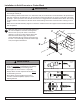
Installation and Assembly: Full Service Video Wall Mount Model: DS-VW765-POR Max UL Load Capacity: 125 lb (57 kg) 1 of 12 ISSUED: 05-13-11 SHEET #: 145-9012-8 2013-06-25
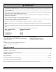
NOTE: Read entire instruction sheet before you start installation and assembly. WARNING • Do not begin to install your Peerless product until you have read and understood the instructions and warnings contained in this Installation Sheet. If you have any questions regarding any of the instructions or warnings, for US customers please call Peerless customer care at 1-800-865-2112, for all international customers, please contact your local distributor.
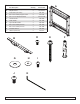
A Parts List A Part Description pull-out mount assembly B adapter bracket 2 145-T1670-1 C mesh sleeve (not shown) 1 600-1014 D M5 x 10mm socket pin type-F screw 2 520-1164 E #14 x 2.
Installation to Wall Stud WARNING • Installer must verify that the supporting surface will safely support the combined load of the equipment and all attached hardware and components. • Tighten wood screws so that wall plate is firmly attached, but do not overtighten. Overtightening can damage the screws, greatly reducing their holding power. • Never tighten in excess of 80 in. • lb (9 N.M.). • Make sure that mounting screws are anchored into the center of the stud.
Installation to Solid Concrete or Cinder Block WARNING • When installing Peerless wall mounts on a concrete wall, the wall must be at least 8” thick with a minimum compressive strength of 2000 psi. • When installing Peerless wall mounts on a cinder block wall, the cinder blocks must meet ASTM C-90 specifications and have a minimum nominal width of 8”. Do not drill into mortar joints! Be sure to mount in a solid part of the block, generally 1” (25 mm) minimum from the side of the block.
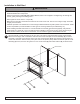
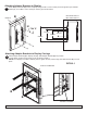
Attaching Adapter Brackets to Display 2 Attach adapter brackets (B) to back of display using four M6 x 12 mm socket pin screws (I) with nylon shoulder washer (H), or four M8 x 15 mm socket pin screws (J) as shown below. DISPLAY B MAX VESA-400 mm MIN VESA-200 mm H I or J 400 mm 600 mm 300 mm 200 mm Attaching Adapter Brackets to Display Carriage 3 Attach adapter brackets (B) to display carriage. Slide adapter brackets (B) into position.
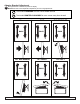
Pull Out Mount Assembly Adjustment Use legend below to determine position of display. 4 NOTE: Each knob can be adjusted independently for fine tuning adjustments.
Adapter Bracket Adjustment legend below to determine position of display. 5 Use NOTE: Each knob can be adjusted independently for fine tuning adjustments.
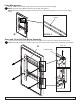
Cable Management 6 Display cables can be routed through top or bottom of pull-out mount assembly (A). NOTE: Use mesh sleeve (M) and cable ties (L) for cable management. NOTE: Cable ties and cable management slots on pull-out mount assembly (A) can be used to secure display cables. CABLE MANAGEMENT SLOTS A DETAIL 3 Open and Close Pull Out Mount Assembly 7 Open pull-out mount assembly (A) by releasing locking tab. Push or pull up on locking tab as shown below.
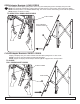
OPEN Adapter Brackets: LONG CORDS 8 Open adapter brackets (B) by pulling down on the long cords while pulling bottom of display away from wall. NOTE: Kick stand will automatically engage. Make sure kick stand is in down postion before resting the display. NOTE: Extended position is for service access only. The mount must be closed during normal use and operation. NOTE: Display not shown for clarity.
Pull-Out Mount Assembly (Optional) Security 9 To prevent locking tabs from releasing, secure using two M5 x 10 mm socket pin type-F screws (D).
Optional for Multiple Displays: Installing Spacer Kit (Sold Separately) NOTE: Spacer Kit not Evaluated by UL 10 Slide spacers into tab of mounted wall plate as shown. Keeping spacers flush against wall plate, fasten two #10 x 3/4" wood screws as shown. There must be two spacers placed on the same side as the additional wall plate. Align the tabs of the additional wall plate flush with the spacers. Follow main instruction for proper installation of additional wall plates.