I N S T A L L A T I O N DX8100 Series Digital Video Recorder SCSI Card and External Video Storage C3648M (7/08)
Contents Important Safety Instructions . . . . . . . . . . . . . . . . . . . . . . . . . . . . . . . . . . . . . . . . . . . . . . . . . . . . . . . . . . . . . . . . . . . . . . . . . . . . . . . . . . . . . . . . . . . . 5 Introduction . . . . . . . . . . . . . . . . . . . . . . . . . . . . . . . . . . . . . . . . . . . . . . . . . . . . . . . . . . . . . . . . . . . . . . . . . . . . . . . . . . . . . . . . . . . . . . . . . . . . . . . . . . 6 About the External Storage Upgrade . . . . . . . . . . . . .
List of Illustrations 1 2 3 4 5 6 7 8 9 10 11 12 13 14 15 16 17 18 19 20 21 22 23 24 25 26 27 28 29 30 31 32 33 34 35 36 37 38 39 40 41 42 43 44 45 46 47 48 49 50 51 52 53 C3648M (7/08) Removing the Power Cord . . . . . . . . . . . . . . . . . . . . . . . . . . . . . . . . . . . . . . . . . . . . . . . . . . . . . . . . . . . . . . . . . . . . . . . . . . . . . . . . . . . . . . . . . 9 Removing the Chassis Cover . . . . . . . . . . . . . . . . . . . . . . . . . . . . . . . . . . . . . . . . . . . . . . .
C3648M (7/08)
Important Safety Instructions The DX8100-ISCI SCSI card must be installed inside the DX8100 chassis. To do so, the DX8100 must be taken offline and turned off before starting the upgrade process. Before continuing the upgrade procedure, read these safety instructions. 1. Read the Important Safety Instructions that came with the DX8100. You can access this document at www.Pelco.com.
Introduction Welcome to the external video storage upgrade for the DX8100 Series digital video recorder (DVR). The external video storage upgrade includes the DX8100-ISCI SCSI card and the DX8100HDDI (Infortrend® EonStor® A12U-G2421). These two items are ordered and shipped separately. The DX8100HDDI includes a 3.3 ft (1 m) SCSI cable and other parts for its installation. Before you upgrade the system, familiarize yourself with the instructions in this manual.
Parts List and Tools DX8100-ISCI SCSI CARD Qty 1 1 1 Description DX8100-ISCI SCSI card ESD Grounding wrist strap DX8100-ISCI SCSI Card and DX8100HDDI Installation manual (C3648M) To install the DX8100-ISCI SCSI card, you will also need a nonmagnetic Phillips screwdriver #1, a properly grounded ESD wrist strap and mat, and four small containers (optional) to store screws.
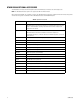
OTHER DX8100 OPTIONAL ACCESSORIES The DX8108 base unit includes an 8-channel capture card and the DX8116 base unit includes a 16-channel capture card. NOTE: The DX8100-ISCI SCSI card option is not supported for DX8124 or DX8132 models. Before upgrading the DX8100, refer to Table B, for a list of other DX8100 accessories that can be installed with the external video storage. Items not listed are not supported in combination with the DX8100-ISCI SCSI card and DX8100HDDI options. Table B.
DX8100-ISCI SCSI Card Installation NOTE: When ordered together, the DX8100 and DX8100HDDI units come preconfigured from the factory. The DX8100-ISCI SCSI card is already installed and the units are ready for installation. Proceed to Installing a New DX8100 and DX8100HDDI System on page 15. If you are upgrading an existing DX8100 System, perform the following steps. PREPARING THE SCSI CARD FOR INSTALLATION 1. Unpack the DX8100-ISCI SCSI card kit. 2.
OPENING THE CHASSIS WARNINGS: • Make sure the unit is turned off and you are wearing a properly grounded ESD wrist strap before attempting to open the chassis cover. • The chassis assembly includes parts with sharp edges. To avoid injury, use caution when working in and around the DX8100 chassis and components. 1. Make sure you protect the unit and its components, which are susceptible to damage from improper handling and ESD.
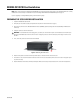
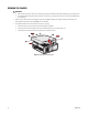
UNDERSTANDING THE COMPONENT LAYOUT Figure 3 and Table B provide information about the DX8100’s slot assignments and major components. (Slots on the motherboard are labeled differently.) REAR OF DVR FRONT OF DVR Figure 3.
MOVING THE MAIN CAPTURE CARD In the DX8108 and DX8116 base DVRs, the main capture card is installed in slot 2. To install the DX8100-ISCI SCSI card, the main capture card must be moved from slot 2 to slot 3. The DX8100-ISCI SCSI card must be physically installed in slot 2. To move the main capture card from slot 2 to slot 3: 1. Prepare the main capture card for removal (refer to Figure 4): a. Remove the rear cross-brace. b. Remove the slot cover for slot 3 and retain the screw. c.
2. Move the main capture card (refer to Figure 5): a. Remove the capture card from slot 2 and firmly seat the capture card in the PCI connector for slot 3. b. Secure the capture card bracket with the screw. c. Reconnect the 5-wire TV/Audio cable. d. Reconnect the 7-wire TV/Audio cable. e. Reconnect the 2-wire audio cable. NOTE: You will reattach the 32-pin ribbon cable after you install the SCSI card. Figure 5.
REASSEMBLING THE UNIT 1. Replace the chassis cover using the screws you removed from the sides and rear of the unit (refer to Figure 7). Figure 7. Replacing the Chassis Cover 2. Attach the silver product label that came with your upgrade kit to the inside of your DVR’s front door. a. Remove the paper backing from the product label. b. Carefully place the label, adhesive-side down, on a free section of the inside of the door. c.
Installing a New DX8100 and DX8100HDDI System When ordered together, the DX8100 or DX8116 and DX8100HDDI units come preconfigured from the factory. The DX8100-ISCI SCSI card is already installed and the units are ready for installation. INSTALLING THE UNITS NOTES: • When installing the DX8100 and DX8100HDDI units, make sure they are close to one another. The SCSI cable is 3.3 ft long (1 m) and must easily connect both units. • Both units are very heavy.
3. Install the drive trays: a. On the DX8100HDDI front panel, place the drive tray 1 release button in the unlocked position (refer to Figure 10). KEY-LOCK RELEASE BUTTON Figure 10. Drive Tray Key-Lock in Unlocked Position b. Press the release button (refer to Figure 11). The front flap opens. Figure 11. Opening the Drive Tray Door Using the label on the drive tray, install the drive tray in the drive bay labeled with the same number (refer to Figure 8 on page 15). OPEN c. Figure 12.
CONNECTING THE DX8100HDDI TO THE DX8100 Refer to Figure 13 to perform the following steps: 1. Plug one end of the VHDCI-to-VHDCI SCSI cable into port CH 1/A on the DX8100-ISCI SCSI card. 2. Plug the other end of the SCSI cable to the DX8100HDDI CH0-In connector. 3. Insert both DX8100HDDI power supply cords in to the unit and plug the cords in to a wall socket.
Upgrading the DX8100 with the DX8100HDDI The DX8100HDDI upgrade comes preconfigured from the factory and does not need to be configured during the installation process. However, you need to configure the DX8100 to recognize and work with the newly installed DX8100HDDI. NOTES: • When installing the DX8100HDDI, make sure it is close to the DX8100. The SCSI cable must easily connect to both units. • Both units are very heavy; two people are needed to lift and carry each unit. HARDWARE INSTALLATION 1.
9. When the Computer Management window appears, click Disk Management. 10. If the “Initialize and Convert Disk Wizard” appears, perform the following steps. Otherwise, go to step 11. Figure 16. Initialize and Convert Disk Wizard a. Click Next, and make sure all disks are selected. Figure 17. Verifying All Disks are Selected C3648M (7/08) b. Click Next again. All disks should still be selected. c. Click Next, and then click Finish.
d. Disk status appears in the contents pane. For this example, there are five unallocated dynamic drives. Perform the following steps: (1) Right-click a disk in the Disk status pane (one that is labeled Dynamic). A shortcut menu appears. (2) Select “Convert to Basic Disk.” Figure 18. Unallocated Dynamic Drives e. Repeat step 10d until all drives are converted to the Basic status. 11.
a. Configure any unallocated drives. (1) Right-click the first unformatted disk in the contents pane (labeled Unallocated). A shortcut menu appears. (2) Click New Partition. Figure 20. Unallocated Dynamic Drives b. Perform a quick format. (1) Click Next four times. (2) Select the “Perform a quick format” check box. (3) Click Next, and then click Finish. Figure 21.
12. Repeat step 11 until all unformatted disks are formatted. Once formatted, the disk status changes from Unallocated to Healthy. Figure 22. HDD Format Status 13. Perform one of the following options: • Disable the DX8100 internal storage: To store video data only on the DX8100HDDI, you must disable data from being stored on the DX8100’s internal HDDs. To do this, perform steps 14 and 15.
15. Click Close to exit the Computer Management application. 16. Start the Allocation Management application. a. Go to Start > Run. The Run dialog box appears. b. In the Open drop-down box, type allocreset. c. Click OK. 17. The Security Warning dialog box appears. Click Run. Figure 24. Security Warning 18. The Allocation Management dialog box appears. Click Re-Allocate. Figure 25. Allocation Management 19. A completion message appears. Perform the following steps: a. Click OK. b.
20. If you are storing video data on the DX8100 internal HDDs and the DX8100HDDI, click the Recovery button. Figure 26. Selecting the Recovery Option 21. Click the plus (+) to display the available partitions. Figure 27. Viewing Available Partitions 22. Select the Allocate option on all partitions: a. Click the “Not used” button. A shortcut menu appears. b. Click Allocation. Figure 28.
23. Repeat step 22 until all partitions are set to Allocation. 24. After all partitions are set to Allocation, click “Begin allocation.” 25. When the warning message appears, click Yes. After all partitions are allocated, the DX8100 application automatically starts and begins recording data to the DX8100’s internal storage (if not disabled) and to the DX8100HDDI.
Upgrading the DX8100HDDI HDD Storage Capacity The DX8100HDDI must be reconfigured when upgrading the storage capacity. WARNING: Adding additional drives to the DX8100HDDI to increase its storage capacity requires that the RAID array be deleted and rebuilt. Doing so removes all recorded video data, which cannot be reversed or recovered. BACKING UP RECORDED VIDEO DATA (OPTIONAL) 1. Back up the video data stored on the DX8100HDDI.
6. At the command prompt, type telnet and the DX8100HDDI’s IP address obtained in step 4c, and then press Enter. Figure 30. Entering the Telnet IP Address 7. When prompted for the password, press Enter again. 8. Press Esc on the keyboard to close any messages. 9. Select PC Graphic , and then press Enter. Figure 31. PC Graphic ANSI Mode 10. Unmap all partitions: a. Select “view and edit Host luns,” and then press Enter. A shortcut menu opens and “CHL 0 ID 0” is highlighted. C3648M (7/08) b.
Figure 32. Unmapping Partitions 11. On the keyboard, press Esc twice to return to the Main Menu. 12. Select “view and edit Logical drives,” and then press Enter. Figure 33.
a. Verify that the active Logical Drive is selected, and then press Enter. b. Choose “Delete logical drive,” and then press Enter. Figure 34. Delete Logical Drive c. Select Yes on the shortcut menu, and then press Enter. 13. On the keyboard, press Esc twice to return to the Main Menu. INSTALLING THE NEW HDDS NOTE: You do not have to shut down the DX8100HDDI to install the new hard drives. 14. Install the new HDDs in the DX8100HDDI drive bays.
19. Press and hold ENT for two seconds to initialize the logical drive. PWR BUSY MUTE ATTEN ESC ENT Figure 36. Initializing Logical Drive UNMAP THE LOGICAL DRIVE 20. After the logical drive is initialized, press the down arrow three times until “View and Edit Host Luns” appears. PWR BUSY MUTE ATTEN ESC ENT Figure 37. View and Edit Host Luns 21. Press ENT three times until Delete CH0 ID0 LUN=00 Mapping appears (refer to Figure 38). PWR BUSY MUTE ATTEN ESC ENT Figure 38. Delete LUN 22.
PARTITIONING THE LOGICAL DRIVE 27. On the keyboard, press Esc to close any messages. The Main Menu appears. 28. Select PC Graphic , and then press Enter. Figure 39. PC Graphic ANSI Mode 29. From the Main Menu, select “view and edit Logical drives,” and then press Enter. Figure 40. View and Edit Logical Drives 30. The first entry in the logical drives table is selected. Press Enter. Figure 41.
31. Select “Partition logical drive” on the shortcut menu, and then press Enter. Figure 42. Partition Logical Drive 32. A warning message. Select Yes, and then press Enter. Figure 43. Partition Logical Drive Warning 33. Set the partition size for the first logical drive: a. Select the logical drive you want to partition, and then press Enter. b. In the partition size text box, type 1740800, and then press Enter. Figure 44.
c. A warning message appears. Select Yes, and then press Enter. Figure 45. Starting the Partition Process 34. Set the partition size for the remaining logical drives: a. In the logical drives table, select the next logical drive in the list. b. Press Enter. c. In the partition size text box, type 1740800, and then press Enter. d. A warning message. Select Yes, and then press Enter. Figure 46. Partitioning the Next Drive 35.
MAPPING THE PARTITIONS 37. From the Main Menu, select “view and edit Host luns,” and then press Enter. A shortcut menu appears. Figure 48. Main Menu 38. Select “CHL 0 ID 0” and press Enter. A second shortcut menu appears. 39. Select Logical Drive, and then press Enter. Figure 49.
40. Press Enter four times. 41. The Map Logical Drive prompt appears. Select Yes, and then press Enter. Figure 50. Accepting LUN 0 (Zero) Mapping Settings 42. Select LUN 1, and then press Enter twice. 43. Select the next available partition, and then press Enter twice. NOTE: Mapped partitions are indicated by an asterisk (*) in the partition column. Figure 51. Selecting the Next Partition 44. Select Yes at the Map Logical Drive prompt, and then press Enter. Figure 52. Accepting LUN 1 Mapping Settings 45.
46. After all partitions are mapped, press Esc on the keyboard to return to the Main Menu, and then close the command prompt. Figure 53. LUN Mapping FORMATTING THE DRIVES 47. Return to the DX8100HDDI front panel and press ESC five times. The Ready status appears in the LCD window. 48. Make sure the DX8100 is still connected to the DX8100HDDI, and turn on the DX8100. The DX8100 application window appears. 49. Access the Windows operating system on the DX8100: a. Log on to the DX8100. b.
55. To perform a quick format: a. Click Next four times. b. Click the “Perform a quick format” check box. c. Click Next, and then click Finish. 56. Repeat step 54 until all drives are formatted. Once formatted, the disk status changes from Unallocated to Healthy. 57. Click Close to close the Computer Management application. ALLOCATING THE NEW DX8100HDDI DRIVES 58. Start the DX8100 Allocation Management application: a. Go to Start > Run. The Run dialog box appears. b.
Specifications ELECTRICAL Input Voltage 100 VAC (at 6 A) to 240 VAC (at 3 A) ±10%, 50/60 Hz, with PFC (autoswitching) Cable Type 2 USA (117 VAC), 2 European (220 VAC), 2 UK (250 VAC) All, 3 prongs, molded connector, 6 ft (1.8 m) cord Power Consumption Maximum 720 W MECHANICAL Connectors VHDCI Stereo Mini Jack RJ-45 2 Ultra SCSI ports COM 1 10/100 Mbps Ethernet GENERAL Operating Temperature 32° to 104°F (0° to 40°C) Relative Humidity Maximum 95%, noncondensing Dimensions Desktop Rack Mount 19.
PRODUCT WARRANTY AND RETURN INFORMATION WARRANTY Pelco will repair or replace, without charge, any merchandise proved defective in material or workmanship for a period of one year after the date of shipment. Exceptions to this warranty are as noted below: • Five years on fiber optic products and TW3000 Series unshielded twisted pair (UTP) transmission products. • Three years on Spectra® IV products. • Three years on Genex® Series products (multiplexers, server, and keyboard).
Worldwide Headquarters 3500 Pelco Way Clovis, California 93612 USA USA & Canada Tel: (800) 289-9100 Fax: (800) 289-9150 International Tel: +1 (559) 292-1981 Fax: +1 (559) 348-1120 www.pelco.