I N S T A L L A T I O N Endura® GW5000 Gateway C2694M (7/08)
Contents Regulatory Notices . . . . . . . . . . . . . . . . . . . . . . . . . . . . . . . . . . . . . . . . . . . . . . . . . . . . . . . . . . . . . . . . . . . . . . . . . . . . . . . . . . . . . . . . . . . . . . . . . . . . 7 Video Quality Caution . . . . . . . . . . . . . . . . . . . . . . . . . . . . . . . . . . . . . . . . . . . . . . . . . . . . . . . . . . . . . . . . . . . . . . . . . . . . . . . . . . . . . . . . . . . . . . . . . . 7 Security Notice . . . . . . . . . . . . . . . . . . . . . . .
Appendix A: Replacing the Operating System Drive . . . . . . . . . . . . . . . . . . . . . . . . . . . . . . . . . . . . . . . . . . . . . . . . . . . . . . . . . . . . . . . . . . . . . . . . . 35 Appendix B: Updating Software . . . . . . . . . . . . . . . . . . . . . . . . . . . . . . . . . . . . . . . . . . . . . . . . . . . . . . . . . . . . . . . . . . . . . . . . . . . . . . . . . . . . . . . . . 36 Appendix C: Configuring Internet Explorer . . . . . . . . . . . . . . . . . . . . . . . . . . . . . . .
List of Illustrations 1 2 3 4 5 6 7 8 9 10 11 12 13 14 15 16 17 18 19 20 21 22 23 24 25 26 27 28 29 30 31 32 33 34 35 36 37 Sample GW5000 Gateway Application Scenario. . . . . . . . . . . . . . . . . . . . . . . . . . . . . . . . . . . . . . . . . . . . . . . . . . . . . . . . . . . . . . . . . . . . . . . . . 8 Major Package Components. . . . . . . . . . . . . . . . . . . . . . . . . . . . . . . . . . . . . . . . . . . . . . . . . . . . . . . . . . . . . . . . . . . . . . . . . . . . . . . . . . . . . . .
List of Tables A B C D E 6 Incoming Port Configuration on the Private LAN . . . . . . . . . . . . . . . . . . . . . . . . . . . . . . . . . . . . . . . . . . . . . . . . . . . . . . . . . . . . . . . . . . . . . . . . 20 Outgoing Port Configuration on the Public WAN . . . . . . . . . . . . . . . . . . . . . . . . . . . . . . . . . . . . . . . . . . . . . . . . . . . . . . . . . . . . . . . . . . . . . . . . 20 Port Configuration on the Public WAN. . . . . . . . . . . . . . . . . . . . . . . . . . . . . .
Regulatory Notices This device complies with Part 15 of the FCC Rules. Operation is subject to the following two conditions: (1) this device may not cause harmful interference, and (2) this device must accept any interference received, including interference that may cause undesired operation. RADIO AND TELEVISION INTERFERENCE This equipment has been tested and found to comply with the limits of a Class A digital device, pursuant to Part 15 of the FCC Rules.
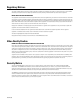
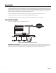
Description The GW5000 gateway delivers video from the Endura network to users communicating through a public network with limited bandwidth, such as a Local Area Network (LAN), Wide Area Network (WAN), or the Internet. Endura technology provides high quality digital images by using high resolution, high frame rate video streams. These video streams often exceed the bandwidth capabilities of public networks.
Before You Begin Endura is a network system that requires a continuous amount of bandwidth to transmit true, live video. Therefore, always include your network administrator when planning and installing Endura components.
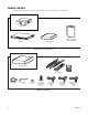
PACKAGE CONTENTS The following diagrams show the contents of the three boxes. When installing the GW5000, refer to these diagrams. SHIPPING BOX NET5000 SAFETY INSTRUCTIONS INSTALLATION MANUAL ACCESSORY PACK Figure 2. Major Package Components ACCESSORY PACK RACK MOUNT KIT FRONT BEZEL KEY 2 EA. SECURITY TOOL 1 EA. RUBBER FEET 4 EA. PHILLIPS PAN HEAD SCREW, 8-32 X 0.25-INCH 4 EA. USA STANDARD POWER CORD (110 VAC) 1 EA. UK STANDARD POWER CORD (250 VAC) 1 EA.
REAR MOUNT RAIL 2 EA. RACK MOUNT KIT FRONT MOUNT RAIL 2 EA. CHASSIS MOUNTING BRACKETS 2 EA. SHOWN ACTUAL SIZE PHILLIPS FLAT HEAD SCREW, 6-32 X 0.25-INCH 6 EA. PHILLIPS TRUSS HEAD SCREW, 8-32 X 0.375-INCH 6 EA. PHILLIPS FLAT HEAD SCREW, 10-32 X 0.5-INCH 4 EA. PHILLIPS PAN HEAD SCREW, 10-32 X 0.5-INCH 4 EA. CAGE NUT, 10-32 10 EA. Figure 4.
Equipment Placement and Rack Mounting The GW5000 can be placed on a flat surface, such as a desktop, or mounted in an equipment rack. PRODUCT SERIAL NUMBER LABEL PLACEMENT Product serial number labels help identify your system and its factory configuration in the event that your GW5000 or its components require service. Three labels citing your product’s serial number are attached to your GW5000. One large label is attached to the bottom of the GW5000.
RACK MOUNTING The GW5000 mounts into an industry-standard 19-inch (48 cm) equipment rack. The GW5000 occupies one rack unit (1.75 inches or 4.5 cm) of vertical rack space. The hardware necessary to mount the GW5000 into a rack is supplied with the unit. The rack must meet the following requirements: • 19-inch (48 cm) EIA-310-D compliant (rear column required). • Rack column depth: 24 to 30 inches (61 to 76 cm).
3. Attach one front-mount rail to one rear-mount rail. Make sure the rails are mounted back to back, as shown in Figure 8. Use three 8-32 x 0.375-inch Phillips truss head screws for each rail set. Leave the screws loose until step 8. (3) SCREWS, 8-32 X 0.375 PHILLIPS TRUSS HEAD Figure 8. Assembling a Support Rail 4. Repeat step 3 for the other rail set. 5. If you are installing the unit into a square-hole rack: Insert 10 cage nuts into the square-hole rack as shown in Figure 9.
6. Attach one support rail assembly to the equipment rack in the desired location (refer to Figure 10): NOTE: The support rail assemblies are identical and may be used on either the right or left side of the rack. a. Position the ear of the front-mount rail against the front of the equipment rack. Align the top and bottom holes in the ear of the rail with the threaded holes (or cage nuts) in the rack. b. Using two 10-32 x 0.
9. Place the unit onto the mount rails by sliding the chassis brackets onto the rails. The unit should slide in and out of the rack easily. MADE IN USA FREQ: 50/60 Hz AMPS: 0.7 VOLTS: 100-240 ~ WARNING: When sliding out the GW5000, be careful not to let the unit fall out of the rack. SN: Figure 11. Mounting the GW5000 into the Rack 10. After the unit is in place, tighten the two thumbscrews to secure the unit to the rack. THUMBSCREW Figure 12.
Connections MADE IN USA FREQ: 50/60 Hz AMPS: 0.7 VOLTS: 100-240 ~ Familiarize yourself with the GW5000 rear panel before connecting any equipment to the unit. SN: Figure 13. Rear Panel Layout ì Power Switch î Power Connector ï Not Used ñ Network Connector (private) ó Network Connector (public) CONNECTING POWER The GW5000 uses an autoranging power supply that automatically adapts to voltages between 100 VAC and 240 VAC (50/60 Hz).
Operation The GW5000 gateway manages all connections with NET5301-TC transcoders. When the gateway receives a request from a Web client to send a video stream, the gateway determines whether the video needs to be routed through a transcoder to covert the video into a format that can be used by the Web client. After the video transmission has been completed, the gateway releases the transcoder until it is needed again.
u Unit Status Unit status is indicated by one of the following three colors: • Green: The unit is functioning normally. • Amber: The unit is in configuration mode. • Red: The unit is in an error condition (refer to Appendix F: Troubleshooting on page 40). If the unit status indicator is flashing, the unit is in one of three modes (refer to Table E on page 40). REAR PANEL INDICATORS There are two indicators on the private network connector on the rear panel.
Network Configuration Endura distributed, network-based products are available only to certified dealers or integrators. Contact your local sales representative for details on certification applications and requirements. Additional information on Endura products and certifications may be found on the Endura partner portal at http://www.pelco.com/endura.
CONFIGURING THE WAN FIREWALL Each video stream that the gateway transmits to the Web client uses a unique destination port that is assigned sequentially. The WAN firewall must be capable of passing each video stream that arrives from the gateway. Each port on the WAN firewall must be open so that video streams can pass through to the Web client. These ports can be configured on the firewall to forward transmissions automatically.
RESOLVING ROUTER SOURCE ADDRESS AND PORT TRANSLATION Both the LAN and WAN firewalls can perform network address and port translations on data transmissions as they leave the firewall. The network address translation (NAT) address and port are the required destination for data transmissions that enter a firewall from a public Internet location.
Configuring the Endura Gateway The Endura gateway requires separate configuration apart from the Endura system. Only users who have been assigned the role Administrator can perform configuration tasks. LOGGING ON TO THE WEB CLIENT FOR THE FIRST TIME The Web client can be opened in either the 32-bit or 64-bit version of Internet Explorer. Microsoft ActiveX® is required to view video in the Web client. However, ActiveX cannot be installed in the 64-bit version of the browser.
ENTERING THE PRIVATE NETWORK INTERFACE HOST INFORMATION 1. From the Setup page, select Private Network Interface. 2. Enter or select the appropriate information for your LAN site: • Host Name • DHCP (enable or disable DHCP for the system) • IP Address • Subnet Mask • Gateway • DNS Server IP 3. If you have more than one domain name system server IP address, enter them on separate lines. 4.
ADDING DEVICE NETWORK ADDRESSES The Endura gateway is designed to recognize all available devices that are connected to the Endura system. If you notice a camera is not available, you can add its network address. 1. From the Private Network Interface page, click the Test button below the Existing Networking table (refer to Figure 21). The gateway polls the Endura system and lists the network address and machine bitmask for each device that has not been recognized automatically. 2.
CONFIGURING THE NETWORK DIRECTORY INTERFACE 1. From the Setup page, select Network Directory Interface (refer to Figure 22). 2. Enter the appropriate information. Contact your system administrator for the following information:. • IP Address: The IP address of the network directory (for example, 192.168.100.3). • Distinguished Name (DN): The naming attributes of each level of the object domain tree (for example, dc=gdn, dc=pelco, dc=prg).
ESTABLISHING EVENT ARCHIVE SETTINGS Use the Event Archive page to configure the settings for archiving events. Figure 23. Event Archive Page 1. From the Setup page, select Event Archive. 2. Select one Archive Method, either Max No. of Records or Time Interval. • Max. No. of Records: The Gateway system will retain a specific number of event records, then archive them and delete them from the table.
MAINTAINING THE GATEWAY Use the Gateway Maintenance page to restart the daemon, reboot the system, or restore the default database. WARNINGS: • Performing any of these actions (restart, reboot, or restore) will impact the system and available data, as well as interrupt workflow. • Do not perform any of the steps in this section without careful consideration. Do not restore the database default without discussing the step with Pelco Product Support.
REBOOTING THE GATEWAY Rebooting a gateway shuts down and restarts the system. Consider rebooting the gateway if you have restarted the gateway daemon (refer to Restarting the Gateway Daemon on page 28) but still cannot view video stream or lists. 1. Click the Reboot button. You will not receive a confirmation message. The system proceeds immediately to reboot. Unsaved data will be lost and must be reentered. 2. Restart the browser and log on to the Web client again.
SENDING BROADCAST MESSAGES Use the Broadcast Message page to create a message to be sent to users by e-mail and instant message (IM). Before a broadcast message can be sent, perform the following functions: • Configure the IM server and e-mail server. Refer to Configuring the E-Mail Server on page 29. • Enter the e-mail addresses for users. Refer to Setting User Attributes on page 33. Figure 27. Broadcast Message Page 1. From the Setup page, select Broadcast Message. 2.
TESTING NETWORK DIRECTORY CONNECTION 1. Click the Test LDAP button to test the network directory connection. A message appears confirming the success or failure of the test. Figure 30. LDAP Test Results Messages 2. Click OK to return to the Gateway Maintenance page. 3. If the test failed, check the network directory setup. Refer to Configuring the Network Directory Interface on page 26.
Configuring Users on the Web Client The Web client provides a single default user role for administrators. All additional roles must be created from the WS5000 advanced system software. Refer to Choosing a Role on page 33 for instructions on assigning roles to a user. NOTE: Only users who have been assigned the Administrator role can create and update users. Figure 31. Configuring Users CREATING A USER 1. On the Setup page, select User from the Type list. A list of users appears on the page. 2.
EDITING USER ATTRIBUTES AND ROLES SETTING USER ATTRIBUTES After creating the user name and password (refer to Creating a User on page 32), the Attributes section of the page lists the most commonly used attributes. Set the values for these attributes for this new user (or modify values for existing users). Figure 32. Attributes Section of New User Page 1. Click any attribute in the Attribute Name list. Notice that its name appears in the Attribute Name field. 2.
ADDING GATEWAYS If more than one gateway is connected to the Endura system, you can specify those which each user can access from the Web client. Once set, these gateways are listed in the Gateway List on the Video page when the user logs on. Figure 34. Gateway Section of New User Page 1. From the list of gateways available, click the gateways the user is permitted to access. (To select more than one Gateway at a time, press and hold the CTRL key on the keyboard while selecting each gateway.) 2.
Appendix A: Replacing the Operating System Drive The GW5000 uses a compact flash drive for the unit operating system. In addition to greater reliability, this drive can be easily replaced if a failure occurs. NOTES: • You must shut down the unit to replace the operating system drive. • The unit uses a hex button socket security screw to prevent tampering. This procedure requires the enclosed operating system drive security tool. Contact Pelco for the new operating system drive.
Appendix B: Updating Software Endura administrators can update software quickly and easily on remote devices directly from the WS5000 advanced system software or the Endura utilities. For instructions on using the Endura utilities, refer to the Endura Utilities Installation/Operation manual (C1672M). Follow these instructions to update the software on the GW5000 from the WS5000 advanced system software. 1.
Appendix C: Configuring Internet Explorer You must install the ActiveX Control on Internet Explorer if you intend to view video on the gateway Web client. This installation is required only on the initial use of the Web Client. 1. Open the browser. 2. Select Tools from the menu bar. 3. Select Internet Options. 4. In the Internet Options dialog box, click the Security tab. 5. On the Security tab, click the “Trusted sites” icon, and then click the “Sites” button. 6.
Appendix D: Working with Multiple Gateways You can set up multiple gateways if your network includes Active Directory. The Active Directory is used to provide a global authentication of the user and to control the assignment of gateways to the user. To perform these functions, a new attribute called ‘pelco-gatewayURL’ stores the gateway URL. This attribute must be attached to the gateway computer and the user classes. A computer object must be created for each gateway in the system.
Appendix E: Bandwidth Selection The following table provides information about bandwidth usage for viewing video from computers with different Internet connection types. Use this table to determine if you have sufficient available bandwidth to view full-stream video from your computer. If your computer provides limited bandwidth, this table can help you determine which lower bandwidth to select to view transcoded video. Table D.
Appendix F: Troubleshooting If the following instructions fail to solve your problem, contact Pelco Product Support at 1-800-289-9100 or 1-559-292-1981 for assistance. Access the properties dialog boxes for the GW5000. Then note the following information before contacting Pelco: • Unit serial number: Located on the label on bottom of the GW5000. • Software version: Located on the Advanced Properties dialog box in the WS5000 advanced system software. WARNING: Do not try to repair the unit yourself.
Specifications MODEL NUMBER GW5000 Interface between Endura system and a public network with limited bandwidth VIDEO/AUDIO Video Standards NTSC/PAL/EIA/CCIR composite Video Compression MPEG-4 Video Streams 2, simultaneous per input Video Resolutions 4CIF 2CIF CIF NTSC 704 x 480 704 x 240 352 x 240 PAL 704 x 576 704 x 288 352 x 288 NETWORK Interface (private) 1 Gigabit Ethernet RJ-45 ports (1000Base-T) Interface (public) 56 kbps to 100 Mbps (100Base-T) FRONT PANEL INDICATORS/FUNCTIONS Power B
PHYSICAL Construction Steel cabinet Finish Bezel Chassis Gray metallic with black end caps Black matte finish Dimensions 16.7" D x 17.0" W x 1.7" H (42.4 x 43.2 x 4.3 cm) Unit Weight 13.35 lb (6.1 kg) Mounting Desktop (feet) Rack, 1 RU per unit (Rack ears and screws provided) WEB CLIENT SYSTEM REQUIREMENTS Minimum Recommended Processor Intel® Pentium® M 1.6 GHz Intel Core™ 2 Duo 2.
PRODUCT WARRANTY AND RETURN INFORMATION WARRANTY Pelco will repair or replace, without charge, any merchandise proved defective in material or workmanship for a period of one year after the date of shipment. Exceptions to this warranty are as noted below: • Five years on fiber optic products and TW3000 Series unshielded twisted pair (UTP) transmission products. • Three years on Spectra® IV products. • Three years on Genex® Series products (multiplexers, server, and keyboard).
Worldwide Headquarters 3500 Pelco Way Clovis, California 93612 USA USA & Canada Tel: (800) 289-9100 Fax: (800) 289-9150 International Tel: +1 (559) 292-1981 Fax: +1 (559) 348-1120 www.pelco.