® WIRETR ON AUX 1 AUX 3 PAN AUTO CAM ON 2 4 MAN OFF UP LEFT RIGHT ZOOM FOC US IRIS TELE NEA R OPEN DOWN WIDE FAR CLOSE ON OFF MPT8000 Series Wiretron Digital Transmitter/ Controller and WX8000 Series Receiver/Driver Installation/ Operation Manual C585M-B (11/98) Pelco • 3500 Pelco Way, Clovis • CA 93612-5699 USA In North America and Canada: Tel (800) 289-9100 or FAX (800) 289-9150 International Customers: Tel (1-559) 292-1981 or FAX (1-559) 348-1120
CONTENTS Section Page 1.0 GENERAL .................................................................................................. 5 1.1 IMPORTANT SAFEGUARDS AND WARNINGS ............................... 5 1.2 UNPACKING INSTRUCTIONS .......................................................... 6 1.3 RECOMMENDED TOOLS ................................................................. 6 2.0 DESCRIPTION .......................................................................................... 7 2.1 MODELS .....
LIST OF ILLUSTRATIONS Figure 1 2 3 4 5 6 7 8 9 10 11 12 13 14 Page Basic Wiretron System Configuration ................................................ 9 Multiple Camera Wiretron System ..................................................... 9 Circuit Board Electrical Connections ................................................ 10 24 VAC Power Input Modification Diagram ....................................... 11 Basic Wiretron Interconnect Diagram ...............................................
(This page intentionally left blank.
1.0 GENERAL 1.1 IMPORTANT SAFEGUARDS AND WARNINGS Prior to installation and use of this product, the following WARNINGS should be observed. 1. Installation and servicing should only be done by qualified service personnel and conform to all local codes. 2. Unless the unit is specifically marked as a NEMA Type 3, 3R, 3S, 4, 4X, 6, or 6P enclosure, it is designed for indoor use only and it must not be installed where exposed to rain and moisture. 3. Only use replacement parts recommended by Pelco. 4.
1.2 UNPACKING INSTRUCTIONS Unpack and inspect all parts carefully. The following items are supplied: 1 MPT8000 Series Wiretron Controller or 1 1 WX8000 Series Receiver/Driver Installation/Operation Manual (C585M-B) Be sure to save the shipping carton, boxes and inserts. They are the safest materials in which to make future shipments. If an item appears to have been damaged in shipment, replace it properly in its box and contact the factory at 1-800-289-9100 or 1-559-292-1981 for a replacement.
2.0 DESCRIPTION The Wiretron digital control system operates over a two-conductor cable and controls CCTV equipment such as pan/tilts, enclosures, and motorized zoom lenses from a remote location up to 10 miles (16 km) away. Wiretron can be configured to control a single site or interfaced with Pelco video switching equipment to provide a convenient video/control system with multiple control sites and/or multiple camera sites. The Wiretron control system provides up to 15 remote control functions: 1. 2. 3.
2.1.
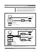
3.0 INSTALLATION The simplest Wiretron system, consisting of the control transmitter and receiver, is shown in Figure 1. Up to 15 control functions are transmitted over the transmission line to the remotely located receiver. These signals are then converted to drive voltages or relay switching for auxiliary equipment being controlled. The basic system can be expanded to control multiple camera sites with the addition of a manual video switcher with balanced audio follow (BAF), as shown in Figure 2.
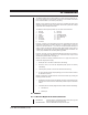
3.1 RECEIVER 24 VAC POWER INPUT MODIFICATION The WX8024RX series receivers can be converted to operate with 24 VAC input. To convert the receiver, disconnect the receiver circuit board and assembly from the enclosure. The patch panel circuit board is located on the bottom of the receiver circuit board mounting plate and requires the following modifications for 24 VAC operation (refer to Figures 3 and 4.) NOTE: Parts needed for modifi- cation: one 3 A fuse for F3.
1 P6 66 94V0 9648 T3 T2 24V P/T 28VCT 24V CAM J2 3 T1 110V 5 6 2 J2 3 J3 5 110V 6 220V 220V 4 1 110V 8 8 8 J4 J5 J6 9 9 9 GND J4 J5 J6 F1 F2 J3 220V 4 110V 110V 1 5 6 2 4 110V J1 7 J2 3 J3 1 J1 7 J1 7 BLUE/WHITE YELLOW BLUE F3 1 P7 T3 BROWN/WHITE BROWN BLACK/WHITE CUT WIRES SHORT AND INSULATE BLACK RED RED/WHITE WHITE GREEN BLACK BLUE VIOLET 24 VAC INPUT 24 VAC OUTPUT F2 CAM 1A F3 P/T 3A Figure 4.
3.2 MOUNTING 3.2.1 Transmitter/Controller NOTE: Never mount the receiver with wiring connectors facing up. Always have the connectors facing down to prevent water damage. Transmitter/controllers in the MPT8000 Series are desktop units. Determine the best location for the unit. Proceed to Section 3.2.2, RECEIVER. 3.2.2 Receiver NOTE: When installing the WX8000 receiver to a wall outdoors, seal the bolt holes with an appropriate sealant.
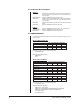
CAUTION: HAZARDOUS VOLTAGE MAY EXIST WX8000 SERIES RECEIVER 22 3 AC LOW 2 GND 1 AC HIGH AC INPUT F3 1 P3 TEST MODULE CX900TLC HI LOW AUTO/RANDOM SCAN MODULE A9000 GND F2 F1 J2 PS 1 8 HI LOW GND 10 1 P2 P1 1 14 MPT8000 SERIES CONTROLLER TB1 HI LOW GND AC INPUT Figure 5. Basic Wiretron Interconnect Diagram 3.3.1.2 Wiring from the Receiver/Driver to the Pan/Tilt 1. Run multi-conductor cable between the receiver/driver and the pan/tilt (refer to Figures 1 and 2.) 2.
3. Slide the connector pins into the appropriate holes in the connector body until they snap into place. Refer to Figures 4 and 5 for correct pin arrangement, depending on model and options. 4. Push the connector clamp assembly (with boot, if used) toward the connector body. Screw the clamp assembly onto the connector body, being careful not to disturb the wires. 5. To complete the assembly, attach the appropriate clamp with the screws provided and tighten. 6.
RECEIVER CONTROL INPUT PIN ASSIGNMENT RECEIVER CONTROL OUTPUT PIN ASSIGNMENT P1 3 BRN P/T COM 1 5 ORG LEFT 3 4 N/C 8 1 9 5 15 10 22 4 16 28 23 7 GRN DOWN 5 6 BLU UP 6 4 VIO RIGHT 7 9 GRAY GROUND 8 12 BLK IRIS 10 1 11 W/BRN FOCUS 11 3 10 W/RED ZOOM 12 2 14 W/ORG LENS COM 13 4 13 RED MAN IRIS 2 5 1 WHITE CAM AC HIGH 9 CAMERA W/YEL CAM AC LOW 14 POWER 10 BRN/W N/C 28 9 RED/W N/C 29 8 ORG/W AUX 1 30 7 YEL/W N/C 31 6 GRN/W
3.3.2 Auxiliary Functions WARNING: Mechanical relays used must not exceed 10 VDC at 25 mA. Applications with higher power requirements should be used with the AUX2000 Auxiliary Control Box. Refer to the AUX2000 manual for installation and operation instructions. The Wiretron receiver is capable of operating up to four remotely activated auxiliary functions. Each auxiliary output may be individually converted at the receiver for momentary or latching operation.
WIRETRON Figure 9. Auxiliary Functions Wiring Diagram + 12 VDC NORMALLY-OPEN CONTACTS WIRETRON RECEIVER/DRIVER 37-PIN CONNECTOR 10 VDC RELAY 1N4005 CURRENT MAXIMUM 1 2 MANUAL IRIS NOTE: CUSTOMER SUPPLIES PARTS AND 12 VDC POWER SUPPLY 3 8 25 mA COIL CONNECT TO NEGATIVE SIDE OF 12 VDC SUPPLY GROUND Figure 10.
3.3.3.1 Long Distance Cable Installation Because of the many options available, long distance video wiring is at your discretion. Review the following to determine the best method of wiring video for your application. Maximum Distance Recommendations for Coaxial Cable There are a number of variables to consider when specifying the type of coaxial cable to run. It is best to avoid the use of video amplifiers. Video amplifiers should be regarded as a remedy for an existing problem not as an installation aid.
Fiber Optic Cabling Fiber optic transmission of both video and control presents some distinct advantages. Higher quality and longer distance transmission characteristics, inherent noise resistance, greater flexibility for usage, and reduced cabling diameter are but a few of these advantages. The incorporation of fiber optics systems are encouraged, especially when covering long distances and when seeking to maintain the highest quality video signals.
Table B. Video Coaxial Cable Wiring Distances Cable Type* Maximum Distance RG59/U RG6/U RG11/U 750 ft (229 m) 1,000 ft (305 m) 1,500 ft (457 m) *Minimum cable requirements: 75 ohms impedance All-copper center conductor All-copper braided shield with 95% braid coverage Table C. 24 VAC Wiring Distances The following are the recommended maximum distances for 24 VAC applications and are calculated with a 10-percent voltage drop.
4.0 OPERATION In general, all controller operating controls are self-explanatory. All controls, except the ON/OFF power switch, are center-off, spring return switches (momentary onoff-momentary on.) When using Aux 1-4 in the latching mode, operating the switch once will latch the function and operating it again will unlatch the function. The camera on/off switch is non-functional; the receiver is permanently in the ON condition. Reset causes latching functions to revert to the following: 1. Manual scan 2.
5.0 MAINTENANCE Regularly scheduled maintenance is not required. Clean the outer surface of the controller or receiver with a non-abrasive cleaning cloth and antistatic cleaner. Do not use kerosene or similar substances that may damage the surface. 6.0 TROUBLESHOOTING If you experience operating problems with either the controller or receiver, first check all fuses and voltage readings to make sure they are in working order.
6.1 Receiver Pin Assignments Refer to Figure 11, Receiver Pin Assignments, when servicing the receiver.
7.0 SPECIFICATIONS MPT8000 CONTROLLER ELECTRICAL Input Voltage MPT8000CZ: MPT8000CZ/220: 120 VAC, 60 Hz 230 VAC, 60 Hz Power Consumption: 2.
GENERAL Construction and Finish: Black polyester powder coated steel Operating Temperature: 32° to 120°F (0° to 49°C) Dimensions: See Figure 12 Weights MPT8000CZ MPT8000CZ/220 Unit 7.5 lb (3.36 kg) 7.5 lb (3.36 kg) Shipping 8 lb (3.62 kg) 8 lb (3.
Connectors Receiver Input: Receiver Output: Fuse Protection WX8024RX, WX8024RXI 3-contact terminal block 37-pin AMP CPC for control output (mate supplied) Fuse 1: Not used Fuse 2: 2/10 A, 3AG, slow blow fuse Fuse 3: 1 A, 3AG, slow blow fuse WX8024RX/220, WX8024RXI/220 Fuse 1: Not used Fuse 2: 1/10 A, 3AG, slow blow fuse Fuse 3: 1/2 A, 3AG, slow blow fuse WX8115RX Fuse 1: 2/10 A, 3AG, slow blow fuse Fuse 2: 2/10 A, 3AG, slow blow fuse Fuse 3: 1 A, 3AG, slow blow fuse WX8220RX Fuse 1: 1/10 A, 3AG, slo
9.44 (23.98) 4.32 (10.97) 8.00 (20.32) NOTE: VALUES IN PARENTHESES ARE CENTIMETERS; ALL OTHERS ARE INCHES 7.00 (17.78) 6.00 (15.24) 10.75 (27.31) 10.00 (25.40) 11.31 (28.73) 11.62 (29.51) O .31 (.79) [4X] Figure 13. WX8000 Series Receiver Dimension Drawing (Outdoor Models) 7.87 (19.99) 5.09 (12.93) 4.18 (10.62) 9.75 (24.76) 11.25 (28.58) 10.50 (26.67) 4.18 (10.62) NOTE: VALUES IN PARENTHESES ARE CENTIMETERS; ALL OTHERS ARE INCHES Figure 14.
8.0 WARRANTY AND RETURN INFORMATION WARRANTY Pelco will repair or replace, without charge, any merchandise proved defective in material or workmanship for a period of one year after the date of shipment. Exceptions to this warranty are as noted below: • Five years on FT/FR8000 Series fiber optic products. • Three years on Genex® Series products (multiplexers, server, and keyboard).