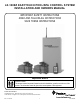
LX-100EZ EASYTOUCH POOL/SPA CONTROL SYSTEM INSTALLATION AND OWNERS MANUAL IMPORTANT SAFETY INSTRUCTIONS READ AND FOLLOW ALL INSTRUCTIONS SAVE THESE INSTRUCTIONS Important Notice Attention Installer. This manual contains important information about the installation, operation and safe use of this product. This information should be given to the owner/operator of this equipment. Pentair Pool Products 1620 Hawkins Ave., Sanford, NC 27330 • (919) 774-4151 10951 West Los Angeles Ave.
INSTALLATION MANUAL IMPORTANT SAFETY INSTRUCTIONS ............................................................................... 5 SYSTEM INCLUDES ............................................................................................................................... 5 EQUIPMENT LOCATION ..................................................................................................................... 5 RECOMMENDED HYDRAULIC SCHEMATIC ..............................................................
OWNER’S MANUAL IMPORTANT SAFETY INSTRUCTIONS ............................................................................ 21 INTRODUCTION .................................................................................................................... 22 SAFETY FEATURES .............................................................................................................. 22 HEATER PROTECTION ..........................................................................................................
This page is blank. P/N 520050 4 Rev.
INSTALLATION MANUAL LX-100EZ EASYTOUCH POOL-SPA CONTROL SYSTEM IMPORTANT SAFETY INSTRUCTIONS READ AND FOLLOW ALL INSTRUCTIONS CAUTION All wiring must be performed by a qualified electrician. Basic safety precautions and local codes should always be followed when installing and using this electrical equipment. WARNING To reduce the risk of injury, do not permit children to use this product unless they are closely supervised at all times. CAUTION The Hand-held Remote is not waterproof.
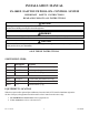
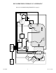
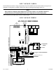
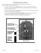
P/N 520050 6 BLOWER SPA JET JET AIR PUMP INTAKE CP-100 CONTROLLER (OPTIONAL) SPA-SIDE REMOTE SPA LIGHT 5 CVA-24 1 9 6 SUCTION CLEANER WATER SENSOR SKIMMER 2 FILTER PUMP LX-100 RF POWER/LOAD CENTER FILTER MAIN DRAIN POOL LIGHT POOL CLEANER PUMP 8 HEATER 3 CVA-24 4 RECOMMENDED HYDRAULIC SCHEMATIC Refer for “PLUMBING REQUIREMENTS” on page 7. Rev.
PLUMBING REQUIREMENTS Plumb system in accordance with “RECOMMENDED HYDRAULIC SCHEMATIC” on page 6, local codes and the following guidelines. Bring all lines back to the equipment pad. 1. Spa should be at or above the level of the pool. If spa is attached to pool, provide a dam between the two bodies of water to allow spa overflow into pool. If spa is not attached to pool, an overflow, sufficient in size to carry full pump-flow, must be installed at water level in the spa. 2.
LX-100 RF POWER/LOAD CENTER Select a convenient location to mount the LX-100 RF Power/Load Center. Ensure that the location is greater than 5 feet from the water’s edge and no further than 15 feet from any motorized valves (otherwise Valve Actuator cables will need to be extended). The top of the LX-100 RF Power/Load Center should be a minimum 5 feet above the ground and a minimum 8 feet from any air blower to optimize RF signal reception.
LOW VOLTAGE CABLES Install cable between the low voltage compartment of the LX-100 RF Power/Load Center and the various pieces of equipment. Provide plastic or metallic conduit where cables run underground, through concrete, etc. Note Never install low voltage and high voltage wires in the same conduit. It is advisable to maintain a minimum distance of 12” between parallel runs of low voltage and AC current-carrying wires. Valve Actuators are provided with 15 feet of 3-conductor cable.
RECEIVER CIRCUIT BOARD Mounted to the back of the LX-100 RF Power/Load Center is the Receiver Circuit Board. On the circuit board, you will discover the following: 1. A 4-position configuration switch (designated S2), which can be used to configure an automatic countdown cycle for the Spa and/or the Aux1 circuit. (Aux1 is designated as button “A” on Hand-held Remote). See page 13 for details. 2.
CUSTOMIZING THE COMMUNICATION LINK The communication link between the Receiver and Hand-held Remote can be customized to prevent interference to or from other RF systems. To accomplish this, there is a 10-position configuration switch located on the Receiver circuit board and inside the Hand-held Remote. Units are shipped from the factory with all switches in the “ON” position.
VALVE ACTUATORS Remove knob, handle and four screws from cap of valve(s) to be motorized, and use the four mounting screws provided to mount Valve Actuator(s) to valve(s). Run cables to low-voltage wiring compartment of LX-100 RF Power/Load Center, and plug into circuit board at the appropriate Valve Socket: Plug intake (suction) valve into INT VLV Socket. Plug return valve into RET VLV Socket. Plug auxiliary valve (if applicable) into AUX VLV Socket.
HEATER CONNECTIONS DUAL THERMOSTAT GAS HEATER/HEAT PUMP Inside the heater, connect three 18 AWG wires in parallel with the heater toggle switch or in accordance with the Heater Manufacturer’s instructions. Do not disconnect or bypass the flow, pressure or high limit switches. Place the heater toggle switch in the “OFF” position, and set the thermostats to desired pool and spa temperatures. Run the three wires to low-voltage compartment of LX-100 RF Power/Load Center.
SYSTEM OPTIONS AUTOMATIC COUNTDOWN CYCLE There is a 4-position configuration switch (designated S2) located on the Receiver circuit board. This switch can be used to set a countdown cycle (time-out feature) for the Spa and/or Aux1 circuit. Once this feature has been enabled, the equipment will automatically turn off after the countdown cycle irrespective of how the circuit was turned on (by Hand-held Remote or optional Indoor Remote, or Spa-side Remote).
SPA-SIDE REMOTE CONTROL The optional Spa-side Remote Control is a double-insulated device which is ETL-listed for installation within 5 feet of the water’s edge. It is typically installed at the tile-line of the spa wall (above water level), or in the deck within arm’s reach of the spa. If the Spa-side Remote is to be installed into the wall of a gunite spa, provision should be made while the spa is being plumbed. See “RECOMMENDED HYDRAULIC SCHEMATIC” on page 6.
POOL CLEANER For systems which incorporate a booster pump pool cleaner, it is possible to add a mechanical time clock for programming the daily cleaning cycles. Install 24-Hour Time Clock (model TMR-LX) into LX-100 RF Power/Load Center faceplate at the POOL CLEANER location, and plug into top of circuit board at CLNR TIMER socket, in accordance with instructions provided.
WATER TEMPERATURE SENSOR For use with optional Indoor Control Panel only. Select a convenient location to mount the Temperature Sensor (model TS-5L) in the plumbing system between the filter pump and the heater. Drill a 5/16” diameter hole in the pipe, and insert the Sensor. Use a screwdriver to open the hose clamp (included). Position clamp over the Sensor, and gently tighten around the pipe. CAUTION Overtightening of clamp can cause deformation of o-ring seal. Run 2-conductor cable (25 ft.
CP-100 (OPTIONAL) INDOOR CONTROLLER 2 qty. separate 150 foot spools of 6-conductor 26 AWG communication cable are provided (one black and one silver) to connect to the CP-100 Controller. NOTE Cable lubricant must be used when pulling these cables through the conduit. Select a convenient location inside the house or other weather-protected area to mount the CP-100 Controller. The overall width of the Controller (with doors open) is 11-½”.
SYSTEM START-UP Apply power to the system. At the LX-100 RF Power/Load Center, verify that the POWER "ON" status light is illuminated, and make sure that all of the Service Switches are in the “AUTO” position. If the status light is not on, check the 3 amp circuit breaker which is located above the faceplate. If the circuit breaker has tripped (indicated by a white tab), push to reset. On the Hand-held Remote, press the “SPA” Push-button to turn the spa on.
CP-100 OPTIONAL INDOOR CONTROL PANEL If the system has an Indoor Controller, verify that there is a TEMPERATURE Display and check that the EQUIPMENT STATUS INDICATORS are functioning when the Push-buttons are activated. If there is no status display, check the connections at each end of the communication cables very carefully. If necessary, crimp new modular connectors to the cables.
OWNER’S MANUAL LX-100EZ EASYTOUCH POOL-SPA CONTROL SYSTEM IMPORTANT SAFETY INSTRUCTIONS READ AND FOLLOW ALL INSTRUCTIONS. CAUTION When operating or servicing this electrical equipment, basic safety precautions should always be observed including the following: WARNING To reduce the risk of injury, do not permit children to use this product unless they are closely supervised at all times. CAUTION The Hand-held Remote is not waterproof. If it accidentally gets submerged, disassemble by removing screw.
INTRODUCTION The LX-100EZ is an electronic control system which is designed to coordinate and operate all of the equipment associated with your swimming pool and spa. The system is comprised of three principle components: 1. Hand-held Remote. 2. Power Center. 3. Motorized Valves (2 qty).
LX-100 RF POWER/LOAD CENTER Located in close proximity to your pool equipment, the LX-100 RF Power/Load Center houses mechanical time clocks for your filter pump and pool cleaner (if applicable), and manual switches for your Pool Serviceperson. FILTER PUMP and POOL CLEANER Time Clocks Check with your Pool Builder or Service Company as to the amount of time required to provide efficient filtration and cleaning of your pool.
SPA Service Switch For normal system operation, keep this Switch in the “AUTO” position. The “FILL” and “DRAIN” positions are used when cleaning the spa. FILTER Service Switch For normal system operation keep this Switch in the “AUTO” position. The “OFF” and “ON” positions allow your Pool Serviceperson to override the FILTER PUMP Time Clock without altering the program.
MOTORIZED VALVES Your control system is designed to activate two motorized valves, which automatically rotate between pool and spa circulation whenever Push-button #1 (SPA) is activated by the Hand-held Remote. These valves are also activated from the “FILL” and “DRAIN” positions of the SPA Service Switch at the LX-100 RF Power/Load Center.
SYSTEM OPTIONS SPA-SIDE REMOTE CONTROL A 4-button waterproof Remote Control may have been installed into the wall of your spa. This will enable you to control the equipment while sitting in your spa. Your Pool Builder should have custom-labeled each button for your specific application. The RED Button duplicates Push-button SPA by the Hand-held Remote (activates the spa circulation). The YELLOW Button duplicates Push-button A by the Hand-held Remote.
INDOOR CONTROLLER Installed in a convenient location inside your house, the Controller gives you fingertip control of all the equipment associated with your swimming pool and spa. Equipment PUSH-BUTTONS #S, #1, #2 and #3 Four Push-buttons are provided for activating the various pieces of equipment. Your Pool Builder has custom-labeled each Push-button for your specific application. Equipment Status Indicators Status Lights are located above each Push-button.
MAINTENANCE CLEANING THE SPA For cleaning or maintenance purposes, it is possible to use the Control System to automatically empty your spa and then to refill with clean water from the Pool. At the Power Center: 1. Set the SPA Service Switch to “DRAIN” position. 2. Set the FILTER Service Switch to the “ON” position. The Spa will begin to drain into the Pool. 3. Before the Spa has completely drained, set the FILTER Service Switch to the “OFF” position. Do not drain the Spa completely or prime will be lost.
TROUBLE-SHOOTING Your Control System is designed to provide years of trouble-free pool and spa enjoyment. However, if at any time your System should behave erratically, consult the following Check List, which should help to alleviate any problems caused by operator error. If you are still unable to solve your particular symptom, refer the situation to a qualified Pool Service Company. GENERAL 1. Check all circuit breakers at electrical sub-panel. 2.
RF TROUBLE SHOOTING TABLE Symptom Possible Cause POWER LED does not light. LX-100 RF Power/Load Center does not have power. Insure power is being supplied and that the LX-100 RF Load/Power Center operates correctly without the receiver installed. Defective cable or connection to the LX-100 RF Power/Load Center. Verify the function of the board using known good cable set. Defective receiver board. Contact factory or service center. COM LINK LED does not light or blink.
For questions, repairs, replacement parts, or information on possible Authorized Service Centers within your vicinity call: Pentair Pool Products ~ 800-831-7133 Or visit us on the Internet at www.pentairpool.com Rev.
SAVE THESE INSTRUCTIONS. Pentair Pool Products 1620 Hawkins Ave., Sanford, NC 27330 • (919) 774-4151 10951 West Los Angeles Ave., Moorpark, CA 93021 • (805) 523-2400 P/N 520050 32 Rev.