ScreenLogic® Video & Lighting Protocol Adapter User’s and Installation Guide ScreenLogic Video & Lighting Protocol Adapter User’s and Installation Guide
i ScreenLogic® Video & Lighting Protocol Adapter kit contents The following items are included in the kit. Kit contents • • • • • ScreenLogic Video & Lighting Protocol Adapter (P/N 520854Z) AC/DC power adapter RJ45 cable DB9M to RJ45 adapter User’s and Installation Guide (this manual) Technical Support Sanford, North Carolina (8 A.M. to 5 P.M. ET) Moorpark, California (8 A.M. to 5 P.M.
1 Contents ScreenLogic Video and Lighting Protocol Adapter Connection Diagram . 2 Connecting the ScreenLogic Video & Lighting Protocol Adapter ............ 3 Installing the ScreenLogic Video & Lighting protocol adapter ................. 4 Configuring the System ....................................................................... 5 Configuring the Video Camera(s) for the first time ................................ 6 Using the Video Camera Interface ........................................................
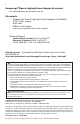
Note: PSC light switches are compatible with incondescent light bulbs only. Lights with florescent light bulbs cannot be used. Camera 1 2 3 4 PCS Light switch(s) found around the home For additional cameras (max qty. 4) an optional Network switch is required.
3 Connecting the ScreenLogic Video & Lighting Protocol Adapter The following describes how to connect the Video & Lighting Protocol adapter to an existing ScreenLogic system. 1. Connect the provided RJ45 (CAT5) cable to an available port (1, 2, 3, or 4) on the ScreenLogic wireless router. Connect the other end of the cable to the LAN port on the Video & Lighting Protocol adapter (see diagram on page 2). 2. Lights cable connection: Connect an RJ45 (CAT5) cable to the COM 1 port on the adapter.
4 Installing the ScreenLogic Video & Lighting protocol adapter Before installing the ScreenLogic software, make sure that you are running the latest version. The latest software version for ScreenLogic can be obtained from the Pentair website at: http://www.pentairpool.com/techinfo/instructions.htm Note: If an existing ScreenLogic system is not present, please install the standard ScreenLogic system first as described in the User’s Guide provided with ScreenLogic.
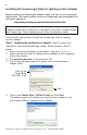
5 Step 2: Updating or installing ScreenLogic Connect software on your PC ScreenLogic Connect is the program that will allow you to configure and operate your IntelliTouch pool/spa control system. 1. 2. 3. Connect the Video & Lighting protocol adapter to port 1, 2, 3, or 4 on your wireless router. Run setup.exe on the installation CD. Follow the prompts to update or install ScreenLogic Connect.
6 3. The software will configure the smaller ScreenLogic Protocol Adapter for use with the Video & Lighting Protocol Adapter. A “System Configuration Complete” message box will be displayed. Click OK to continue with the installation. Please be patient while the Video & Lighting Protocol adapter synchronizes the settings from the IntelliTouch system for the first time. This can take anywhere from 3 to 15 minutes depending upon the complexity of your IntelliTouch system.
7 5. Select the camera manufacture and model and click the OK button. Note: Only configure one camera at a time. For example, connect the first camera, then configure it. Plug in the second camera and repeat. 6. Select the installed video camera model to rename the camera and set its IP address. The cameras IP address must be in the same subnet range as your ScreenLogic Video & Lighting Protocol Adapter. The default IP address for the ScreenLogic Video & Lighting Protocol Adapter is 192.168.2.
8 9. Click the RED X box on the top right side of the dialog to exit the Configuration setup dialog. 10. Click on the Video & Lighting Protocol adapter in the Local System box, then click START. Note: If the Video & Lighting adapter does not show up under the Local Systems, you can manually type in the adapter’s IP address in the System Name field. The adapter’s default IP address is 192.168.2.3 11. Click the Start ScreenLogic button to start the ScreenLogic program.
9 Using the Video Camera Interface The ScreenLogic Video & Lighting Protocol Adapter supports up to four video cameras. Each camera can be accessed by clicking the camera’s name tab at the bottom of the Video screen. Each camera has its own set of controls.
10 Installing Lights for the first time Have the Powerline Interface module ready to connect to COM 1 port on the ScreenLogic Video & Lighting Protocol adapter during the program installation setup. Each light switch must be setup one at a time. WARNING - All switches work must be installed by a licensed electrician, and must conform to the National Electric Code and all national, state, and local codes.
11 5. Click the Add New button. 6. Press the light switch five (5) times in the ON position. The green LED on the light switch will start blinking rapidly which indicates that the light is ready to be configured. See page 2 for connection diagram. 7. Click the OK button on the message dialog box. 8. Rename the light in the “Name” box. Use a name that describes where the light is located. Click the OK button. The light setup procedure will take about one minute for each light fixture. 9.
12 10. Click Done when finished. 11. Click the RED X box on the top right side of the dialog to exit the Configuration setup dialog. 12. Select the Video & Lighting Protocol Adapter in the lower dialog box as shown below. 13. Click the Start ScreenLogic button to start the ScreenLogic program. ScreenLogic Video & Lighting Protocol Adapter address 14. Click the Lighting tab to access the LIGHTING screen.
13 Using the Light Interface The ScreenLogic light screen displays the following light(s) controls.
P/N 520936 - Rev A ScreenLogic Video & Lighting Protocol Adapter User’s and Installation Guide