
Instruction Manual
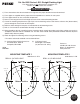
Drill for #8
Screw
Drill for #8
Screw
DRILL 2-1/4” INCH HOLE
MOUNTING TEMPLATE 2
0202 Series L.E.D.
Cat. No. 0202 Series L.E.D. Straight Docking Light
The above lights are not designed for navigational use
and are not for use below the waterline.
MOUNTING INFORMATION
Read all instructions before proceeding.
1). These instructions show the orientation of the light after the proper location has been determined.
2). These lights are supplied with the proper circuit for operation on a nominal 12 volt system.
3). These lights contain no user serviceable components.
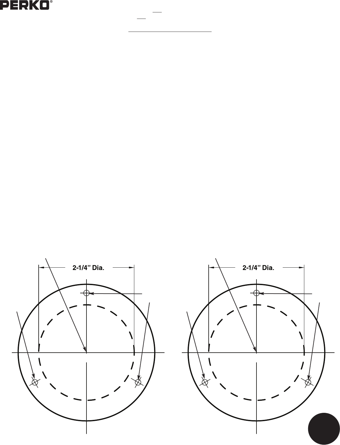
4). Draw a 6 inch long reference line through the center of the selected mounting location.
5). Cut out the mounting template to the right. Tape it on the mounting surface such that the reference line (drawn above)
passes through the exact center of the template.
6). Drill three holes through the template as indicated for the #8 mounting screws.
7). Drill a 2-1/4 inch hole to accommodate the body as indicated.
8). Wiring should be done by a qualified marine electrician. Attach supply connections to the light, making sure to wire in
accordance with both A.B.Y.C. Standard E-9* and U.S. Coast Guard Safety Standards for Boat Electrical Systems
(33CFR 183)* Observe polarity.
9). Attach the light to the mounting surface using #8 mounting screws.
* The above referenced standards can be obtained from:
(1). American Boat & Yacht Council, Inc. (2). U.S. Coast Guard
613 Third Street, Suite 10 Washington, D.C. 20593
Annapollis, MD 21403 (or your local C.G. office)
10/08
0202INS1
Perko, Inc.
16490 N.W. 13th Avenue
Miami, FL 33169-5707
www.perko.com
This is a 3/4”
dia. circle in
order to scale
internet printed
templates
Reference Line
Drill for #8
Screw
Drill for #8
Screw
DRILL 2-1/4” INCH HOLE
MOUNTING TEMPLATE 1
0202 Series L.E.D.
Reference Line