Perle 10GT Media Converter Modules Installation Guide C-10GT-SFP CM-10GT-SFP C-10GT-XFPH CM-10GT-XFPH P/N 5500337-10
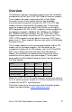
Overview This document contains instructions necessary for the installation and operation of the Perle C/CM-10GT Media Converter modules. These models are used in conjunction with a Perle Media Converter chassis. Each module contains one pluggable transceiver port that permits insertion of a SFP+ or a XFP fiber module and one integrated RJ-45 (copper) port.
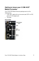
Getting to know your C/CM-10GT Media Converter Your C/CM-10GT Media Converter package consists of the following items: • C/CM-10GT module with one transceiver port (SFP+ or XFP) and one RJ-45 (copper) port.
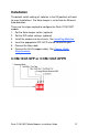
Installation The default switch setting (all switches in the UP position) will work for most installations. The Auto-Jumper is set to Auto for Ethernet Auto detection. These are the steps required to configure the Perle C/CM-10GT module. 1. Set the Auto-Jumper switch. (optional) 2. Set the DIP switch settings. (optional) 3. Install the module into the chassis. See Installing Modules. 4. Insert the appropriate SFP+/XFP into the transceiver port. 5. Connect the fiber cable. 6.
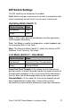
DIP Switch Settings The DIP switches are located on the module. Note: Switch changes made when the module is powered up take effect immediately and will result in a link reset on both ports. Operating Mode (Switch 1) Switch Position Mode Up (default) Data Down Test Data: In Data mode, data will flow between the fiber connection and the copper connection. Test: Test Mode is used to run diagnostics, enable loopback and for running the Built In Link Tests.
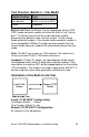
Test Function (Switch 2 – Test Mode) Switch Position Type Up (default) Built In Link Test (BILT) Down Loopback Built In Link Test: Set Switch 2 to the Up position for the C/CM10GT media converter module to initiate the Built In Link Test on port 1. These tests consist of the media converter module generating test patterns to be sent out on port 1 to the remote media converter module.
Sequence of Events 1. The Local C/CM-10GT media converter module sends the Remote C/CM-10GT media converter module a signal to go into test mode. 2. The Remote C/CM-10GT media converter module turns on test mode. 3. Built In Link Test data is sent from the Local C/CM-10GT media converter module to the Remote C/CM-10GT media converter module. 4.
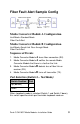
Fiber Fault Alert Sample Config Media Converter Module A Configuration Link Mode–Standard Mode Fiber Fault Alert Media Converter Module B Configuration Link Mode–Smart Link Pass through Mode Fiber Fault Alert Sequence of Events 1. Media Converter Module A loses fiber connection (RX). 2. Media Converter Module A notifies the remote Media Converter Module that there is a fault on the Link. 3. Media Converter Module B detects loss of fiber link on receiver (RX). 4.
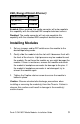
EEE (Energy Efficient Ethernet) Switch Position Mode Up (default) Enabled Down Disabled Enabled: When enabled, the media converter will auto negotiate this capability with the attached EEE compliant devices/servers. Disabled: The media converter will not auto negotiate this capability with the attached EEE compliant devices/servers. Installing Modules 1. Set any jumpers and/or DIP switches on the module to the desired operating mode. 2.
AUTO-Config Jumper (CM models only) The Auto-Config jumper is located on the outer edge, at the midpoint of the module. Jumper the top and middle pin to select Auto mode. Jumper the middle and bottom pin to select SW mode. AUTO: When set to Auto the module will, at power-up, check its internal flash memory to see if configuration information has been downloaded to it from a management module. If so it will use this configuration as its running configuration.
Operation Status LED The Perle C/CM 10GT Media converters modules have three status LEDs located on the faceplate of the module. PWR - Power/Test Green On: Power is on and the module is in normal operation mode. Green blinking slowly: the module is in test or loopback mode. Red blinking slowly while in Test mode: indicates an error within the last second. Red Solid: During power up - hardware error detected. Red Blinking quickly: Error detected. (See LK1 LK2 Error Codes).
LK1- Port 1 Activity On: Fiber link present. Blinking quickly: Fiber link present and receiving data. Blinking slowly: The fiber link has been taken down as a result of Smart Link Pass-Through. Blinking one second on, 3 seconds off: the maximum specified operating temperature within the inserted module has been exceeded. Off: No fiber link present. LK2 – Port 2 Activity On: Copper link present. Blinking quickly: Copper link present and receiving data.
Troubleshooting General Ensure that the SFP+ or XFP module is inserted correctly into the transceiver port. Ensure that the copper cabling (RJ-45) meets Ethernet copper cabling requirements. See Copper Cable Requirements in this guide. No connectivity If unable to get full connectivity with all DIP switches in the UP position, these procedures can be used for troubleshooting. Built In Link Test The Built In Link Test requires two 10GBaseT modules/converters.
Loopback Test This mode is not used in conjunction with BILT. 1. If either media converter module is not a Perle 10GT module then you need to set loopback mode on one of the media converter modules. (See the User’s Guide that came with that media converter module). 2. Use an alternative way to generate data to the unit set in loopback mode. Data received on the receiver (RX) will be looped back to the transmitter (TX) connection. Use a third party application to analyse the received data.
Technical Specifications Power Input/Consumption 9-30VDC SFP+ 1.1A Max, 0.8A at 12VDC Operating Temperature 0°C -50°C (32°F - 122°F) Storage Temperature -25°C -70°C (-13°F -158°F) Operating Humidity 5% to 90% non-condensing Storage Humidity 5% to 95% non-condensing Operating Altitude Up to 3,048 m (10,000 ft) XFP Operating Temperature Storage Temperature Operating Humidity Storage Humidity Operating Altitude Power Input/Consumption 9-30VDC 1.7A Max, 1.
Compliance Information FCC This product has been found to comply with the limits for a Class A digital device, pursuant to Part 15 of the FCC rules. These limits are designed to provide reasonable protection against harmful interference when the equipment is operated in a commercial environment. This equipment generates, uses, and can radiate radio frequency energy and, if not installed and used in accordance with the instructions in this Guide, may cause harmful interference to radio communications.