Perle PoE/PoE+ 10/100/1000 Ethernet Media Converters Installation Guide S-1110P S-1110PP S-1110DP S-1110DPP P/N 5500317-11
Overview This document contains instructions necessary for the installation and operation of the Perle Standalone PoE/PoE+ 10/100/1000 rate converting Media Converters (S-1110P). These products have the ability to convert 10/100/1000Base-T cable connections (copper) to 100/1000Base-X connections (fiber). The Perle media converters function as a PoE switch, and support a variety of port configurations, including single or dual UTP and fiber ports.
PoE (P) PoE+ (PP) Connector (xx) Mode Distance Wavelength (TX/RX) S-1110P-S1SC80U S-1110PP-S1SC80U SC SM 80 km/50 mi. 1510/1590 nm S-1110P-S1SC80D S-1110PP-S1SC80D SC SM 80 km/50 mi. 1590/1510 nm S-1110P-S2xx120 S-1110PP-S2xx120 SC/ST SM 120 km/74.6 mi. 1550 nm S-1110P-S1SC120U S-1110PP-S1SC120U SC SM 120 km/74.6 mi. 1510/1590 nm S-1110P-S1SC120D S-1110PP-S1SC120D SC SM 120 km/74.6 mi. 1590/1510 nm S-1110P-S2xx160 S-1110PP-S2xx160 SC/ST SM 160 km/100 mi.
Dual Copper / PoE (DP) Dual Copper / PoE+ (DPP) Connector (xx) Mode Distance Wavelength (TX/RX) S-1110DP-S1SC80D S-1110DPP-S1SC80D SC SM 80 km/50 mi. 1590/1510 nm S-1110DP-S2xx120 S-1110DPP-S2xx120 SC/ST SM 120 km/74.6 mi. 1550 nm S-1110DDP-S1SC120U S-1110DDPP-S1SC120U SC SM 120 km/74.6 mi. 1510/1590 nm S-1110DP-S1SC120D S-1110DPP-S1SC120D SC SM 120 km/74.6 mi. 1590/1510 nm S-1110DP-S2xx160 S-1110DPP-S2xx160 SC/ST SM 160 km/100 mi.
Installation The default DIP switch settings (all switches in the UP position) will work for most installations. These are the steps required to configure the Perle S-1110P Ethernet media converter: 1. Insert SFP Module (SFP Model only). 2. Set the Auto-MDIX jumper setting (optional). 3. Set the DIP switch settings (if required). 4. Set the Powering Option Jumpers (if required). 5. Install and connect the fiber cable(s). 6. Install and connect the copper cable(s). 7. Power up the media converter.
Power Sourcing Pinouts Note: The factory settings for Power Sourcing Pinouts will work for most installations as 802.3a and 802at-2009 ( POE/POE+) devices will detect and sync to the correct POE option. However, in the rare case that you need to modify the settings, the procedure is below. When Power Sourcing is enabled on a copper port, the S-1110P will provide power to the connected PD device over the Ethernet cable (see PSE function on Dip Switch configurations).
Powering Options Jumper Settings In order to select a powering option, the Power Options Jumper settings must be set. Each copper port has a set of Power Option jumpers. To access the Powering Options Jumper settings, unscrew the six side screws on the case and remove the cover plate. Locate the Power Option jumper set and strap the option pins as detailed below.
DIP Switches The DIP switches are accessible through the opening in the side of the enclosure. Bank 1 Bank 2 Bank 1 Bank 2 Note: All switch changes take effect immediately. Switch changes will cycle power to the PD only if the PD Reset switch is set to On or you make changes to the PSE Power switches.
DIP Switch Settings Bank 1 Auto Negotiation copper (Switch 1) Switch Position Copper 1 Copper 2 Up (default) Auto Auto Down Off Auto Note: Auto negotiation should only be turned off, if the copper link partner does not support Auto Negotiation and fixed settings are required by the copper link partner. Auto: When enabled, the media converter will negotiate with its link partner to determine the most optimal parameters for this connection.
of link on either the fiber or copper port can occur without affecting the other connection. Smart Link Pass-Through In this mode, the link state on one connection is directly reflected through the media converter to the other connection. If link is lost on one of the connections, then the other link will be brought down by the media converter. If the media converter has 2 copper or 2 fiber connections, then both must go down in order to affect the other connection(s).
Illustration of the FFA The following diagram is an illustration of the operation of this feature. (A) – Remote Media Converter setup for Fiber Fault Alert Enabled, Fiber Negotiation – OFF and Link Mode – Standard. (B) – Local Media Converter setup for Fiber Fault Alert Enabled, Smart Link Pass-Through On and Fiber Negotiation - OFF 1 – (A) Loses fiber connection on its receiver. 2 – (A) Sends FFA. 3 – (B) Detects FFA signal and shuts down the fiber link.
Speed copper (Switch 5) Switch Position Copper port 1 Copper port 2 Up (default) 100 NA Down 10 NA Note When Auto Negotiation (SW1) is set to Off, the media converter will use this switch setting for copper port 1 speed. 100: When Switch 5 is in the Up position, the S-1110P will force the speed to 100 Mbps. 10: When Switch 5 is in the Down position the media converter will force the speed to 10 Mbps.
Full Duplex: The Media Converter Module will be set to Full Duplex mode on its fiber link. Half Duplex: The Media Converter Module will be set to Half Duplex mode on its fiber link. Loopback Fiber-1 (Switch 7) Loopback Fiber-2 (Switch 8) Switch Position Mode Up (default) Disabled Down Enabled Disabled: The loopback feature is disabled. This is default position for normal operation. The switch must be set to this position in order for data to pass through the media converter.
Down Down PSE disabled These switches must be set in order to enable the power sourcing function and to indicate the type of device detection required. If the device type is unknown, the default should be used as per IEEE802.3af/at standards. Enabled: When enabled, the media converter will perform Power Sourcing Equipment (PSE) functions as per IEEE802.3af (POE) or 802.3at-2009 (POE+) standards. Disabled: When disabled the media converter will not perform PSE functions.
Fiber Redundancy (Switch 7) Dual fiber models only Switch Position Mode Up (default) Disabled Down Enabled Disabled: When this feature is disabled, both fiber ports will operate as independent ports on a switch. Normal switch rules and functions will apply. Enabled: When this feature is enabled, fiber port 1 will be the primary active fiber connection port and fiber port 2 will be in standby and in an inactive state.
Installing the SFP Fiber Module SFP models only. 1. Locate the appropriate fiber module and insert the SFP into the opening on the front of the media converter. 2. Ensure the SFP module is properly seated. The release latch of the SPF fiber transceiver must be in the closed (up) position before insertion. 3. The SFP module may be inserted before or after applying power to the media converter. 4. Proceed with cable connections. Installing the Duplex Fiber Cable 1.
Installing the Copper Cable 1. Locate 10/100/1000Base-T compliant copper cables with the appropriate connectors. 2. Connect the RJ-45 cable between the Perle media converter and the device. Note: The Perle media converter supports Auto-MDIX which allows connection of a straight-through or cross-over Ethernet cable. See Auto-MDIX Jumper Settings in this guide for jumper positions. Grounding the Media Converter If your installation requires additional grounding the following procedure can be followed.
2. Attach the grounding lug to the chassis and secure with the grounding screw(s). Attaching the Power cord strain relief clip 1. Feed the power cord through the opening in the power cord relief clip. 2. Attach the power cord relief clip to the chassis and secure with the provided screw. 3. Plug the power cord into the AC power connector at the rear of the chassis. 4. Plug the other end of the power cord into an appropriate power outlet. Powering up the Perle Media Converter 1.
Operation Status LED The Perle PoE/PoE+10/100/1000 Rate converting Media converters have status LEDs located on the front panel of the unit. PWR On – Power is applied to the unit Blinking (slow) – Loopback mode (one or both fiber interfaces are in loopback mode) Blinking (fast) Power On failure.
SPD-(Copper Port 1/2) Green – 1000 Mbps Orange – 100 Mbps Off – 10 Mbps (if link is currently established) FDC-1/2 (Duplex on Copper 1/2) On – Full Duplex Mode Off – Half Duplex Mode LKC-1/2 (Link Status on Copper port 1/2) On – Copper link is present Off – No copper link present Blinking (slow) – Copper link appears functional – Copper link has been brought down by Smart Link Pass-Through.
Other Features Auto-MDIX Auto-MDIX (automatic medium-dependent interface crossover) detects the signalling on the 10/100/1000BASE-T interface to determine the type of cable connected (straight-through or crossover) and automatically configures the connection. Pause (IEEE 802.3xy) Integrated Pause signalling is an IEEE feature that temporarily suspends data transmission between two devices in the event that one of the devices becomes overwhelmed with data.
Troubleshooting General 1. 2. 3. 4. Ensure power is supplied to the media converter. Only the Perle provided power supply may be used. Ensure the remote device’s fiber connection type is compatible with the media converter. If using a simplex fiber connection, ensure that you have both an Upstream (U) and Downstream (D) media converter. Ensure all cabling is of the correct type and is in good working order.
converter. At the remote media converter, the data will be looped back and passed through the fiber, back to the local converter and passed to the copper link. No Power to the PD 1. 2. 3. 4. Ensure that the PD is compatible with the S-1110P. If the PD is a POE+ device, a POE+ media converter must be used.
Technical Specifications The following applies to all S-1110P media converters: Power Input / Consumption: 46V DC to 57V DC @ 6 W Operating Temperature: 0°C to 50°C (32°F to 122°F) Storage Temperature: -25°C to 70°C (-13°F to 158°F) Operating Humidity: 5% to 90% non-condensing Storage Humidity: 5% to 95% non-condensing Operating Altitude: Up to 3,048 m (10,000 ft) Dimensions: 150 mm by 95 mm by 26 mm MTBF 1 copper port No Power supply POE POE+ 2 SFP / 1 copper ports 399,432 hours 218,384
PoE (P) PoE+ (PP) Mode Wavelength (nm) TX Power (dB) RX Power (dB) Budget S-1110P-S1SC10U S-1110PP-S1SC10U SM TX: 1310 RX: 1490 Min: -9 Max: -3 Min: -20 Max: -3 11 S-1110P-S1SC10D S-1110PP-S1SC10D SM TX: 1490 RX: 1310 Min: -9 Max: 3 Min: -20 Max: -3 11 S-1110P-S1SC20U S-1110PP-S1SC20U SM TX: 1310 RX: 1490 Min: -8 Max: -3 Min: -22 Max: -3 14 S-1110P-S1SC20D S-1110PP-S1SC20D SM TX: 1490 RX: 1390 Min: -8 Max: -3 Min: -22 Max: -3 14 S-1110P-S2xx40 S-1110PP-S2xx40 SM TX: 1310 RX:
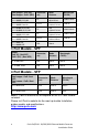
3 Port Models Dual Copper / PoE (DP) Dual Copper / PoE+ (DPP) Mode Wavelength (nm) S-1110DP-M2xx05 S-1110DPP-M2xx05 MM S-1110DP-S2xx10 S-1110DPP-S2xx10 TX Power (dB) RX Power (dB) Budget (dB) TX: 850 RX: 850 Min: -9.5 Max: -4 Min: -17 Max: -3 7.5 SM TX: 1310 RX:1310 Min: -9.5 Max: -3 Min: -20 Max: -3 10.
Dual Copper / PoE (DP) Dual Copper / PoE+ (DPP) Mode Wavelength (nm) S-1110DP -S2xx120 S-1110DPP -S2xx120 SM TX: 1550 RX:1550 S-1110DP -S1SC120U S-1110DPP -S1SC120U SM S-1110DP -S1SC120D S-1110DPP -S1SC120D TX Power (dB) RX Power (dB) Budget (dB) Min: 0 Max: 5 Min: -32 Max: -9 32 TX: 1590 RX:1510 Min: -3 Max: 2 Min: -34 Max: -9 31 SM TX:1510 RX:1590 Min: -3 Max: 2 Min: -34 Max: -9 31 S-1110DP -S2xx160 S-1110DPP -S2xx160 SM TX: 1550 RX:1550 Min: 2 Max: 5 Min: -34 Max: -9 32 S-11
Compliance Information FCC This product has been found to comply with the limits for a Class A digital device, pursuant to Part 15 of the FCC rules. These limits are designed to provide reasonable protection against harmful interference when the equipment is operated in a commercial environment. This equipment generates, uses, and can radiate radio frequency energy and, if not installed and used in accordance with the instructions in this Guide, may cause harmful interference to radio communications.
Warranty / Registration Perle’s standard Lifetime Warranty provides customers with return to factory repairs for Perle products that fail under the conditions of the warranty coverage. Details can be found at: http://www.perle.com/support_services/warranty.shtml Contacting Technical Support Contact information for the Perle Technical Assistance Center (PTAC) can be found at the link below. A Technical Support Query may be made via this web page. www.perle.com/support_services/support_request.