
Owner manual


4
Thank you for purchasing this Price Pster product. All Price
Pster products are carefully engineered, and factory tested
to provide long trouble-free use under normal conditions.
This product is easy to install using basic tools and our easy
to follow illustrated instructions. If you have any questions
regarding this product, see info on previous page.
1 BEFORE PROCEEDING
WARNING: Read all the instructions completely before
proceeding. Price Pster recommends calling a professional
if you are uncertain about installing this product!
This product should be installed in accordance with all local
and state plumbing and building codes.
2 SHUT OFF WATER SUPPLY
Locate water supply inlets and shut off the water supply
valves. These are usually found under the sink or near the
water meter. If you are replacing an existing faucet, remove
the old faucet from the sink and clean the sink surface
thoroughly.
3 ASSEMBLY INSTRUCTIONS
If operating pressures exceed 5 BAR (75 PSI), the use of
a pressure reducer is recommended. Before proceeding
with the assembling, we advise to clean the hot and cold
water tubes, in order to avoid build-up of dirt that could
compromise the functioning of the faucet.
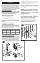
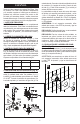
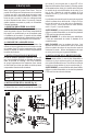
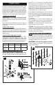
4 VALVE INSTALLATION (Fig.A)
Place the Valve Body (1) into the wall, with the Outlet (2)
facing the up. Body inlets (3&4) and outlet (2) are designed
to accommodate 1/2-14 NPT pipe. Connect the Hot Water
Supply (3) to the Left Inlet and the Cold Water Supply (4) to
the Right Inlet. Connect pipe from Supply Valve Outlet (2)
to Spout Hole. Connect Pipe Elbow (6) and Pipe Nipple (7)
(not included) to end of the pipe as shown.
The Depth is measured from center of Valve Body to
nished wall surface is 1 1/8” to 2 1/2”. Valve Hole on wall
is to be 1 7/8” to 2 1/4” Dia. Spout Hole on wall is to be
1 1/2” to 1 3/4” Dia.
WARNING Iron Pipe Connections:
When attaching
threaded ttings, use thread sealant or PTFE Plumber’s
tape according to manufacturer’s instructions..
CAUTION: When using iron pipes, it is not recommended
to reduce outlet pipe diameter.
CAUTION: For Copper Sweat joints, it is important to
remove Valve Cartridge and other Plastic Components
from the Valve Body before soldering. Use copper pipe
adapters (not furnished) in this type of installation.
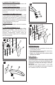
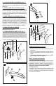
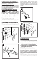
5 TRIM FLANGE ATTACHMENT (Fig.B)
Position Trim Flange (1) with Rubber Gasket (2) onto the
Valve Body (3) and slide ush to wall nish. Secure by
screwing Dome Cap (4) onto Valve Body (3).
ENGLISH
7
2
A
HOT
COLD
B
1
2
3
4
Supply Suggested Maximum Minimum
Hot Water
Temperature
65 Cº (150ºF) 80 Cº (175ºF) 15 Cº (60ºF)
Operating
Pressure
3 BAR (44PSI) 5 BAR (73PSI) 0.5 BAR (7PSI)