
User Manual


ENGLISH
ENGLISH
ENGLISH
7
8
9
10
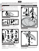
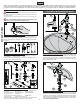
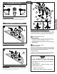
7 VALVE BODY ATTACHMENT
Remove Clip (7A) from Valve Body (7B) and save. From above sink, insert Valve Body
(7B) through Mounting Holes (7C). The HOT valve, labeled with Red Tag (7D), should
be positioned to the left side of the spout.
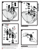
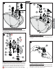
8 VALVE BODY INSTALLATION
Before proceeding, Valve Stems (8A) are to be set in the closed position. From
underneath sink, place Square Washer (8B) onto Valve Shank (8C) and tighten loosely
with Mounting Nut (8D). Temporarily place Handle (8E) onto Valve Stem (8A) to make
sure the handle levers are properly aligned to sink. Remove Handle (8E) and tighten
Mounting Nut (8D) until Valve Body (8F) is fi rmly secured to sink.
Do not use Handles (8E) to tighten or to rotate Valve Bodies (8F)!
9 HANDLE ATTACHMENT
Place Plastic Seal Rings (9A) against the bottom of Handle Hubs (9B). Connect Handles
(9C) onto Valve Adapters (9D).
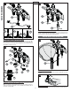
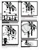
10 SECURING HANDLES
Be sure Valves and Levers are in the "OFF" position. Secure handles by
holding the Lever (10B) in place and tighten the Hubs (10A) by rotating them
in a clockwise direction. To remove handles, rotate Hubs (10A) in a counterclockwise
direction.
3
7B
7D
7C
7B
7A
7B
7C
8C
8A
8A
8B
8D
8E
8F
8B
8D
8F
8C
8E
9A
9C
9D
9A
9B
9C
9B
9D
10B
10A