
Installation Guide


ENGLISH
ENGLISH
12 14
13
15
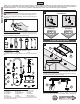
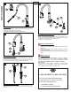
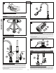
12 PULL-OUT HOSE ATTACHMENT
From underneath sink, remove Protective Cap (12E). Push Quick Connector (12A),
located on the end of the Pull-Out Hose (12B) rmly upward onto the Receiving Tube
(12C), until unable to push any further. Pull down on the Quick Connector (12A). If the
housing and the Inner Collect (12D) separate slightly but do not pull off, the Receiving
Tube (12C) quick connect is secure.
13 SOAP DISPENSER INSTALLATION
From above sink, insert threaded Shank (13A) of soap dispenser body through Foam
Gasket (13B) and sink hole. From below sink, tighten Nut (13C) and thread on Bottle
(13D) to Shank (13A).
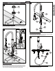
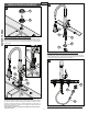
14 SOAP DISPENSER HEAD INSTALLATION
Pour in liquid soap (not included) into the Shank Orice (14A). Insert Pump Mechanism
(14B) into Soap Dispenser Body (14C). Install Dispenser Head (14D) by pushing rmly
onto Pump Mechanism (14B).
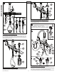
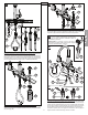
15 WATER SUPPLY CONNECTIONS
A. Thread Inlet Connectors (15A) into Water Supply Lines (15B).
B. Remove Protective Cap (15F). Gently separate hot and cold Faucet Inlets (15C),
approximately 1 in. (26 mm) apart. Connect Water Supply Lines (15B) onto Faucet Inlets
(15C). Hot water supply line goes to hot inlet tting indicated by red tag.
C. Insert Clip (15D) into Inlet Connector Holes (15E) to secure water supply lines, as shown.
Water Supply Lines are not included. Please consult
manufacturer and/or its instructions for the correct method
of installation of supply lines and ttings.
CAUTION: Incorrect application of supply lines and ttings
may result in the failure or leak of the supply lines and ttings.
4
12C
12C
12A
13A
12E
12B
12C
12A
12D
12A
13B
13C
13D
14A
14B
14D
14C
15A
15D
15D
15A
15C
15A
15C
15C
15C
HOT
COLD
15B
15B
1” Max.
(26 mm)
C
A
B
15B
15F
15B
Red Tag
15E