
Installation Guide

ENGLISH
ENGLISH
12
14
15
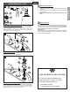
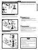
DRAIN BODY INSTALLATION
FAUCET FUNCTIONS
11
13
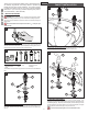
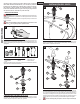
11 HOSE CONNECTION
From underneath sink, push the Center Connector (11A) onto receiving Tube (11B),
until unable to push any further. Pull down on the quick connect housing (11A). If the
housing and the Inner Collet (11C) separate slightly but do not pull off receiving Tube
(11B), the connection is secure.
Slide the End Connectors (11D) with arrow (11E ) pointing up onto the Valve Bodies (11F).
Push the End Connectors (11D) all the way up until completely seated. Be careful not
to damage O-Rings (11G).
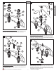
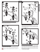
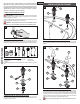
12 WATER SUPPLY CONNECTIONS
First, thread Inlet Connectors (12A) into Water Supply Lines (12B). Then, insert Inlet
Connectors (12A) into Valve Bodies (12C). Hot water supply lines go into left inlet.
Cold water supply lines go into right inlet. (Supply lines not included). Please follow
manufacturer’s instructions when installing supply lines. Next, insert Clips (12D) into
Valve Body Holes (12E), to secure unit.
WARNING: Do not twist Inlet Connectors (12A) once installed!
13 POP-UP INSTALLATION
Install and adjust Pop-Up (13A) using separate instructions supplied with the Pop-Up
assembly.
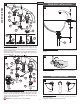
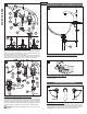
14 UNIT START UP
Turn on hot and cold water supplies, and check for leaks above and below the sink.
15 FAUCET FUNCTION
COLD valve: close-counterclockwise, open-clockwise; HOT valve: close-clockwise,
open-counterclockwise.
Note: Flush faucet before turning on valve (see step 16).
4
HOT
HOT
OPEN OPEN
COLD
COLD
13A
11B
11B
11A
11D
11F
11F
11G
11G
11E
11D
11A
11B
11C
11A
12A
12D
12D
12E
12D
12A
12B
12B
12C
12C