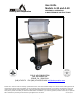
Gas Grills Models A-30 and A-40 R ASSEMBLY, OPERATING & MAINTENANCE INSTRUCTIONS Grills by AEI Corporation (949) 474-3070 PGS BY AEI CORPORATION 2641 DU BRIDGE AVE. IRVINE, CA. 92606-5001 FAX (949) 474-0559 E MAIL info@aeicorporation.com Please note: We have made our catalogs, specification sheets, and other materials relating to our line of outdoor cooking products as comprehensive and accurate as possible.
CONGRATULATIONS! You have purchased a truly exceptional outdoor cooking appliance with your PGS grill from AEI Corporation. Your outdoor gas grill has been designed and constructed to give you many years of outdoor cooking enjoyment. All PGS grills are designed with quality, dependability, performance and safety features not found in any other gas grills. Please read this manual from cover to cover.
TABLE OF CONTENTS Safety Responsibilities, Warning Symbol ............................................................................................... Page 4 Grill Model Identification (Location of Serial Number) ............................................................................ Page 4 Very Important Safety Tips & Warnings ......................................................................................... Pages 5 & 6 Liquid Propane Gas Safety, Connections, Handling and Storage ..........
design could cause changes in the grill that may or may not be included herein. Please consult your authorized PGS dealer if you have any questions concerning assembly, installation or operation of your grill. SPECIAL ATTENTION: THIS SYMBOL NOTES SAFETY RELATED ITEMS OR PRODUCT WARNINGS IT IS YOUR RESPONSIBILITY TO: ASSEMBLE, INSTALL, LEAK CHECK, CARE AND OPERATE YOUR GAS GRILL. SAVE THESE INSTRUCTIONS FOR FUTURE REFERENCE. FOR YOUR SAFETY IF YOU SMELL GAS: 1. SHUT OFF GAS TO THE APPLIANCE. 2.
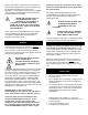
VERY IMPORTANT SAFETY TIPS AND WARNINGS PGS IS MOST CONCERNED ABOUT THE SAFE USE OF OUR PRODUCT. THE FOLLOWING TWO PAGES ARE A SUMMARIZATION OF THE SAFETY TIPS FOUND THROUGHOUT THIS MANUAL. PLEASE TAKE THE TIME TO REVIEW THEM, AS THEY ARE CRITICAL IN THE ENJOYABLE USE OF YOUR GRILL. IMPROPER ASSEMBLY, NEGLECT, OR INSUFFICIENT CARE OF YOUR PGS GAS GRILL MAY RESULT IN SERIOUS BODILY INJURY AND/OR PROPERTY DAMAGE. GIVE THIS SYMBOL SPECIAL ATTENTION THROUGHOUT THIS MANUAL.
• NEVER LEAN OVER HOT GRILL SURFACE OR LOOK DIRECTLY INTO GRILL WHEN ATTEMPTING TO LIGHT. THE GRILL HOOD MUST BE OPENED FULLY WHEN LIGHTING. BE SURE THAT ALL FAMILY MEMBERS ARE AWARE OF SAFE LIGHTING AND OPERATING PROCEDURES FOR THE GRILL. • IF A PROFESSIONAL INSTALLER OR DEALER INSTALLS THE GRILL, BE SURE THAT HE SHOWS YOU WHERE YOUR GAS SUPPLY SHUT OFF IS LOCATED. ALL GAS LINES MUST HAVE A SHUT OFF THAT IS READILY AND EASILY ACCESSIBLE. IF YOU SMELL GAS, CHECK FOR GAS LEAKS IMMEDIATELY.
Check Local Codes. Consult your local LP dealer or Natural Gas Company listed in your local directory for recommended installation procedures and regulations. In the absence of local codes, installation must conform to the National Fuel Gas Code, ANSI Z21.58a-1999*CGA 1.62-M99. grill head. Always turn on the valve at the top of your tank and then the valves to your grill head to the “ON” position.
• Never allow a tank to be overfilled. 100% full tank holds only 4.5 gallons of propane. Inspect your grill cabinet often to ensure that ventilation openings in sides and back of pedestal are free from debris and have proper air circulation. Never paint LP cylinder a dark color. This may cause OVERHEATING. Do not apply heat directly to tank. LP Gas is stored under high pressure and must be handled with care. Do not handle a tank roughly.
VALVE: Device used to control amount of gas (and heat) grill produces. DEFINITION OF KEY TERMS GRILL HEAD: Entire BBQ grill (lid & pit) that can be mounted on a variety of options. ORIFICES: Openings at end of valve that restrict amount of gas going to BBQ. VENTURI: Banana shaped tube that allows gas to flow from the valve to the burner.
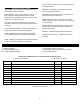
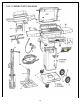
PLEASE NOTE: ALL PARTS MAY NOT COME WITH ALL MOUNTING OPTIONS REF# 1 2 3 4 5 6 7N 7L 8 9 10 11 12 13 14 15 16 17 18R 18L 19 20 21 22 23 24 25 26 27 28 29 30 31 32 33 34 35 37 38 PART NUMBERS AND DESCRIPTIONS DESCRIPTION QTY MODEL A40 UPPER GRILL CASTING 1 140010 LOWER GRILL CASTING WARMING RACK COOKING GRID ROCK GRATE (porcelain) BURNER ASSEMBLY VALVE ASSEMBLY FOR NG VALVE ASSEMBLY FOR LP GAS CONTROL PANEL ONLY SIDE HANDLES BOLT & LOCK WASHER F/HANDLE CERAMIC ROCK CONTROL KNOBS IGNITOR MODULE IGNITOR WIRE
Keep in mind that the gas line access hole is on the back of the post and the notch at the top if facing front. Recheck plumb and allow cement to set. 2. Run the gas supply line into the post access hole (just above the cement). Make a 90° bend to reach the access door opening. The gas supply line should be trenched at least 18 inches below the surface of the ground to prevent damage from digging.
Step 1: Connect the Tank Locking Bar (Fig. 10) Stainless Steel and Aluminum Column To Base Kit Assembly Instructions 1. From box Column Box locate and attach the Tank Lock Bar across the back of the pedestal column. Use the ¾" S.S. Hex bolt, Nylon Lock Bar Spacer and a Kep nut on each side to fasten the Tank Lock Bar in place. This spreads and holds the correct spacing at the back of the column.
Aluminum Column (A-B PED) OPTION: For Portable Base Only A-LC & A-NC: (Fig. 12) 1. Attach the wheels by slipping the axle through the base, slide the wheels on and secure with the axle clips. Finish by snapping the hubcaps on before standing unit upright. For units with casters, place caster stem into stem opening of the portable base, press and snap into place. (Fig. 12) Fig 13A Step 4: Attaching the Access Panel (Fig.
Grill Head Assembly Instructions Step 1: Control Panel & Heat Shield A. Attaching the Heat Shield and Control Panel Assembly (Fig. 19) 1. Attach the complete control panel assembly to the front of the grill head with 1/4—20 Kep nuts. 2. Leave the (2) nuts holding the heat shield on, to serve as spacer nuts. 3. Make sure the valve orifices on the control panel aligns with the burner venturi correctly and that the venturi tubes go over the valve orifices at least 1/4" to 1/2" (see fig. 22 on page 22). C.
C. For Deck/Patio & In-Ground Mounts using 30" Flexible tubing. (Fig. 24) Connect the 30" flexible tube to the incoming gas supply using a 3/8" flare coupling (not supplied). Attach the other end to the grill valve connection behind the control panel. To tighten securely use two wrenches. Hold valve joint with one wrench and tighten the hose fitting with second wrench. After Tighten leak test both connections.
On portable models, this shelf, in the upright position, is to be used as a handle to move the barbecue around. It is a sturdy handle properly hinged securely into place (see Fig. 31). 5. Attach twin lid sides "Stay Cool" handles using 5/16" X 3/4" bolt and star washer, tighten securely. 6. Be certain that grease cup is secure in back of column. 7. Attach two control valve knobs to end of valve stems located in center of control panel. White mark should be pointing up to the OFF position.
Light a long match (or other ignitor) and turn the RIGHT hand control knob to HI. Insert the lit match (or ignitor) into the hole to the end of the burner and light the grill. Under some adverse wind conditions it may be necessary to turn the grill or to light the burner via a vent opening under the grill head. DO NOT TOSS A LIT MATCH INTO THE UNIT AND TURN THE GAS ON! grill housing is heavy rust-free cast aluminum, you are only trying to remove built up grease and debris. 2.
CERTAIN THAT YOUR GAS SUPPLY IS OFF AND YOUR GAS FEED LINE HAS BEEN BLED OF ANY FUEL. WHEN FLASHBACK In many areas, spiders or small insects have been found to create "flashback" problems. The spiders spin webs and/or insects build nests in the grill's venturi tube(s). The web and/or nests can lead to gas flow obstruction, which can damage your grill as it results in a "flashback" (a fire in the venturi tube(s). The grill may still light, but the obstruction does not allow full gas flow to the burner.
in an outdoor appliance operates in a different environment than an indoor appliance burner or flame and as a result will visually look different. If you see the flames lifting from the burner, or only parts of the burner are burning, or if you hear excessive noise from the burner, please check the following: valve/orifice engagement in the venturis, that the burner is level in the casting, and also check burner tubes to be certain they are not obstructed with debris or spider webs.
ALWAYS KEEP YOUR GRILL COVERED WHEN NOT IN USE. ORIFICE ENGAGEMENT YELLOW TIPPING Properly adjusted burner VALVE NORMAL HARD FLAMES VENTURI GAS LINE IN Slightly out of adjustment burner VALVE ORIFICE AIR SHUTTER Figure 38 Proper orifice engagement At the end of each valve there is a tiny gas opening known as an orifice. Gas exits the orifice and enters the venturis where it mixes with air. The proper mixture of gas and air produces a clean blue flame with slight yellow tips from the burner.
No Flame PGS TROUBLESHOOTING GUIDE Gas Shut off Obstruction in Orifice(s) Leak in Gas Train No Gas in Tank or Not Connected to Gas Source Low Flame Leak in Gas Train Obstruction in Orifice(s) or venturi’s Natural Gas valve only turned part way Burner gasket plugging venturis.
PROPER TUBE BENDING Item Hamburgers T-bone or Porterhouse Steaks Amount of Meat 1/2 lb. BEEF COOKING GUIDE (Grill Preheated 5-10 Minutes) Cooking Time Heat for Medium Setting Doneness Medium 8-10 minutes Cooking Tips and Methods Grill with hood closed, turn once 1 to 1.5 lb.
PACIFIC GAS SPECIALTIES COOKING TIPS AND TEMPERATURE GUIDE been designed to heat quickly using minimal amounts of fuel. Cooking on HI with the lid closed is not recommended unless you want to cook very quickly for only a short time. With the lid closed, cooking temperatures will exceed 700 degrees F... that's HOT! Cooking outdoors has truly come of age in America.
INDIRECT COOKING When rotissing you may want to put an aluminum tray or drip pan under the cut of meat to capture the excessive fats and juices to further reduce flare-up. Again, flare-up is desirable when it is under your control. You can bake or roast foods in your PGS grill just like you would in a conventional oven. Casseroles, whole poultry, breads, and cakes can be cooked using this indirect method. As the name implies, the food is not cooked directly over the heat source.
Warranty PLEASE NOTE: ENCLOSED WARRANTY REGISTRATION CARD MUST BE RETURNED TO PGS FOR WARRANTY TO BE IN PLACE. PGS WILL NOT USE WARRANTY INFORMATION FOR ANY PURPOSE OTHER THAN INTERNAL REGISTRATION OR BULLETINS REGARDING PRODUCT IMPROVEMENTS. PGS gas grills are made of the finest materials available. They are designed for use in a residential setting and not intended for commercial installations. Warranty information below applies to residential use.
R Proudly Manufactured by PGS BY AEI CORPORATION 2641 DU BRIDGE AVE. IRVINE, CA. 92606-5001 Office (949) 474-3070 FAX 949 474-0559 E MAIL: info@aeicorporation.