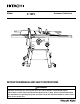
Model C 10FL Stationary Table Saw INSTRUCTION MANUAL AND SAFETY INSTRUCTIONS WARNING Improper and unsafe use of this power tool can result in death or serious bodily injury! This manual contains important information about product safety. Please read and understand this manual before operating the power tool. Please keep this manual available for others before they use the power tool.
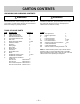
CONTENTS SECTION PAGE Product Specifications ............................................................ 3 Power Tool Safety ................................................................... 4 Table Saw Safety .................................................................... 5 Electrical Requirements and Safety ...................................... 6 Accessories and Attachments ............................................... 7 Tools Needed For Assembly ................................................
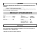
WARNING Some dust created by power sanding, sawing, grinding, drilling and other construction activities contains chemicals known to the state of California to cause cancer, birth defects or other reproductive harm. Some examples of these chemicals are: • Lead from lead-based paints • Crystalline silica from bricks, cement and other masonry products • Arsenic and chromium from chemically treated lumber Your risk from these exposures varies, depending on how often you do this type of work.
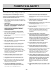
POWER TOOL SAFETY WARNING Before using your table saw, it is critical that you read and understand these safety rules. Failure to follow these rules could result in serious injury or damage to the table saw. Good safety practices are a combination of common sense, staying alert and understanding how to use your power tool. To avoid mistakes that could cause serious injury, do not plug in your power tool until you have read and understood the following safety rules: 1. 2.
TABLE SAW SAFETY 1. ALWAYS USE SAW BLADE GUARD, splitter and antikickback pawls for every operation for which they can be used, including through sawing. Through sawing operations are those in which the blade cuts completely through the workpiece when ripping or crosscutting. 2. ALWAYS HOLD WORK FIRMLY against the miter gauge or rip fence. 3. USE A PUSH STICK when required. Always use a push stick especially when ripping narrow stock.
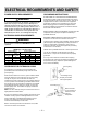
ELECTRICAL REQUIREMENTS AND SAFETY POWER SUPPLY REQUIREMENTS GROUNDING INSTRUCTIONS WARNING To avoid electrical hazards, fire hazards or damage to the table saw, use proper circuit protection. Always use a separate electrical circuit for your tools. This power tool is wired at the factory for 120V operation. Connect it to a 120V, 15 Amp circuit and use a 15 Amp time delay fuse or circuit breaker. To avoid shock or fire, replace the cord immediately if it is worn, cut or damaged in any way.
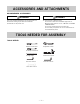
ACCESSORIES AND ATTACHMENTS RECOMMENDED ACCESSORIES WARNING Visit your Hardware Department or see the Power and Hand Tools Catalog to purchase recommended accessories for this power tool. WARNING To avoid the risk of personal injury: Do not use a dado with a diameter larger than 8". Maximum dado width is 13/16". DO N OT U S E W IDE R COMBINATIONS. Do not use molding head set with this saw. Do not modify this power tool or use accessories not recommended by Store.
CARTON CONTENTS UNPACKING AND CHECKING CONTENTS WARNING WARNING Separate all parts from packing materials. Check each part with the illustration on the next page and the “Table of Loose Parts” to make certain all items are accounted for, before discarding any packing material. If any part is missing or damaged, do not attempt to assemble the table saw, plug in the power cord, or turn the switch ON until the missing or damaged part is obtained and is installed correctly.
UNPACKING YOUR STATIONARY TABLE SAW N I H E A J P G O F D K C B AA EE L Q M BB CC DD V W X Y —9— Z
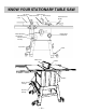
KNOW YOUR STATIONARY TABLE SAW Blade Guard Rip Fence Blade Tilt Scale Miter Gauge Table Extension (Left) Table Extension (Right) Blade Tilting Handwheel Blade Elevation Handwheel ON/OFF Switch with key Leg Stand Castar Table Insert Splitter Table Miter Gauge Storage Rip Fence Storage — 10 —
GLOSSARY OF TERMS HITACHI PROFESSIONAL TABLE SAW TERMS CROSSCUT - A cut made across the width of the workpiece. MITER GAUGE - A guide used for crosscutting operations that slides in the tabletop channels located on either side of the blade. It helps make accurate straight or angle cuts. FREEHAND - Performing a cut without using a fence (guide), hold down or other proper device to prevent the workpiece from twisting during the cutting operation.
ASSEMBLY AND ADJUSTMENTS ESTIMATED ASSEMBLY TIME 50~70 MINUTES (2 PEOPLE) ASSEMBLE STAND (Fig. A) 1. Unpack all parts and group by type and size (Fig. A). Refer to parts list for quantities. 2. Attach one support (4) to leg (1) using one square neck bolt (2) and nut (3). NOTE: Do not tighten bolts until stand is properly aligned (see step # 7). 3. Attach other end of support to another leg using one square neck bolt and nut. 4. Join front frame assemblies using support (5) square neck bolts and nuts. 5.
ASSEMBLY THE TABLE EXTENSION (Fig. C) 1. Place the left table extension next to the saw table, aligning the mounting holes (1). 2. Place bolts (2) and thread in mounting holes. 3. Place a straight edge or combination square on the saw table, across the table extension. 4. Adjust the mounting bolts (2) until the extension is flush with the saw table. Tighten. 5. Repeat these procedures for the right extension table. Fig. C Assembly the rear table rail (Fig. E) 6.
Installing the blade guard assembly (Fig. G) 1. Remove the table insert. 2. Unlock the blade bevel lock knob (1). 3 With the blade evevation handwheel (2), raise the blade to the maximum height. 4. Using the blade tilting handwheel, tilt the blade to 45 on the bevel scale. 5. Lock the blade tilt locking knob. 6. Locate the splitter assembly mounting bracket (4) in back of the blade. 7. Cover the blade teeth with a folded cardboard or position the plastic blade guard over the blade to protect your hands. 8.
REMOVING THE BLADE (Fig. I) WARNING To avoid injury from an accidental start, make sure the switch is in the OFF position and the plug is disconnected from the power source outlet. 1. Remove the table insert and raise the blade to the maximum height by turning the blade elevation handwheel clockwise. 2. Lift the blade guard and position it toward the rear of the table. 3.
6. 7. The, re-loosen the bevel lock handle and reset the blade at the maximum bevel position (45°), then tighten the bevel lock handle. Check again to see if the blade is 45° to the table. If not, repeat step 5. BLADE PARALLEL TO THE MITER GAUGE GROOVE (Fig. M) To avoid injury from an accidental start, make sure the switch is in the OFF position and the plug is disconnected from the power source outlet. This adjustment was made at the factory, but it should be rechecked and adjusted if necessary.
INSTALLING THE TABLE INSERT (Fig. N) The table insert has been previously installed on your unit. However, you must verify that the table insert is flush with the table top surface on all four corners of the insert. Power Cord (Fig. P) For convenience and to prevent damage to the power cord when the table saw is not in use or is being transported, the frame of leg has two brackets (1) on the side for cord atorage. If the table insert is not flush with the table, adjust the four bolts (1) with a 4mm hex.
RIP FENCE ADJUSTMENT (Fig. R) 1. For adjustments, position the fence to the right of the blade, parallel with the miter gauge groove. 2. Place the rear clamp (1) of the fence on the back rail of the table, and lower the front end over the front rail (2). Push the handle (3) down to lock. 3. To change the position of the fence, lift up on the handle to unlock, and slide the fence to the desired position, then push the handle down to lock. Fig. R RIP FENCE INDICATOR (Fig.
OPERATION BASIC SAW OPERATIONS Fig. V RAISE THE BLADE (Fig. U) To raise or lower the blade, turn the blade elevation handwheel (1) to the desired blade height, and then tighten the bevel lock handle (2) to maintain the desired blade angle. 1 Fig. U 1 2 2 3 3 TILTING THE BLADE 1. To tilt the saw blade for bevel cutting, loosen the lock knob (2) and turn the tilting handwheel (3). 2. Tighten the lock knobs (2) to secure. ON / OFF SWITCH (Fig. V) The ON / OFF switch has a removal key.
RIPPING (Fig. W, X) WARNING Keep your thumbs off the table top. When both of your thumbs touch the front edge of the table (2), finish the cut with a push stick. To make an additional push stick, use the pattern on page 26. 8. The push stick (3) should always be used. (Fig. X) 9. Continue pushing the workpiece with the push stick (3) until it passes through the blade guard and clears the rear of the table. 10. Never pull the piece back when the blade is turning. Turn the switch OFF.
CROSSCUTTING (Fig. Y) To prevent serious injury: Do not allow familiarity or frequent use of your table saw to cause careless mistakes. Remember that even a careless fraction of a second is enough to cause a severe injury. Keep both hands away from the blade and the path of the blade. 1. Remove the rip fence and place it in the "storage" compartment of the table saw base. 2. Place the miter gauge either groove in the table top. 3. Adjust the blade height so it is 1/8" higher than the top of the workpiece.
USING WOOD FACING ON THE RIP FENCE (Fig. DD) When performing some special cutting operations, add a wood facing (1) to the side of the rip fence between the fence and the blade where you will be cutting (2). Attach auxiliary fence to rip fence with two "C" clamps. (Fig. FF) Fig. FF 1 . Use a smooth & straight 3/4" thick wood board (1) measure as long as the rip fence is. 2. Attach the wood facing to the fence with wood screw (3) through the hole in the fence.
MAINTENANCE MAINTAINING YOUR TABLE SAW Fig. HH GENERAL MAINTENANCE For your own safety, turn the switch OFF and remove the switch key. Remove the plug from the power source outlet before maintaining or lubricating your saw. 1. Clean out all sawdust that has accumulated inside the saw cabinet and the motor. 2. Polish the saw table with an automotive wax to keep it clean and to make it easier to slide the workpiece. 3. Clean cutting blades with pitch and gum remover. 4.
115V & 230V Wire Wirding Motor (Terminal Block) (BLACK) (BLACK) (BLACK) 2 (BLACK) (Rocker Switch) Blue 1 3 (BLACK) 4 230V 60HZ power A(1) B(2) (BLACK) A(1) C(3) 4 (CIRCUIT BREAKER SWITCH) C(3) (BLACK) B(2) (BLACK) 230V Wire Wirding Green (Motor) (CIRCUIT BREAKER SWITCH) (GROUND) (WHITE) Blue Black 115V 60HZ Power B (Terminal Block) Black 4 4 Brow A(1) B(2) (CIRCUIT BREAKER SWITCH) C(3) Black B(2) A(1) Black C(3) Blue (Rocker Switch) (BLACK) (WHITE) (BLACK) Black 115V
TROUBLESHOOTING GUIDE WARNING To avoid injury from an accidental start, turn the switch OFF and always remove the plug from the power source before making any adjustments. 䢇 Consult Hitachi Authorized Service Center if for any reason the motor will not run. SYMPTOM POSSIBLE CAUSES CORRECTIVE ACTION Saw will not start 1. Saw not plugged in 2. Fuse blown or circuit breaker tripped 3. Cord damaged Does not make accurate 45° and 90° rip cuts 1. Positive stop not adjusted correctly 1. Plug in saw 2.
— 26 — 1/2” Squares. Cut off here to push 1/2” wood. Cut off here to push 1/4” wood. Notch to help prevent hand from slipping. PUSH STICK Optional hanging hole. Make from 1/2” or 3/4” wood or thickness less than width of material to be cut. CAUTION! Use only good strong wood or plywood. Use a jigsaw or bandsaw to cut out.
— 27 —
PARTS LIST 10" STATIONARY TABLE SAW MODEL NO. C10FL Always order by I.D. Number PARTS LIST FOR SCHEMATIC A I.D. 1550 2372 2374 2376 2378 2379 2389 2390 2552 09HZ 09HZ 09JK 0BAC 0BAE 0BB2 0BB2 0DMP 0GD0 0HVX 0J4K 0J4N 0J4N 0J4N 0J69 0JAF 0JC9 0JCH 0JG5 0JH7 0JP3 0JPU 0JUB 0JV3 0JV5 0JX7 0JX7 0JZ4 0K05 0K05 0K0T 0K10 0K17 0K19 0K2C 0K3X 0K3X 0K56 0K61 0K7F 0K7G 0K9P 0K9P 0KA0 0KA0 0KAA 0KAA 0J6T Description CR. RE.COUNT HD.
10" STATONARY TABLE SAW SCHEMATIC A MODEL NO.
10" STATONARY TABLE SAW PARTS LIST FOR SCHEMATIC B I.D. 2494 0CS E 0J 9C 0J B Y 0K 0T 0K 7F 0K 7L 0K J 7 0K M Y 0K PQ 0K QY 0K R R 10LF 10LU 22V0 Description CAU T ION LAB E L POW E R COR D CLAM P S PR IN G W AS HE R PAR ALLE L PIN HE X . HD. S CR E W AN D W AS HE R CR . R E . R OU N D W AS HE R HD. S CR E W CR . R E . R OU N D W AS HE R HD. S CR E W CAP HD. S Q.N E CK B OLT HE X . N U T HE X . N U T N U T CHU CK S ER R ATED TOOTHED HEX AG ON FLANG E NU T HE X .
10" STATONARY TABLE SAW SCHEMATIC B MODEL NO.
Issued by Hitachi Koki Co., Ltd. Shinagawa Intercity Tower A, 15-1, Konan 2-chome, Minato-ku, Tokyo 108-6020, Japan Distributed by Hitachi Koki U.S.A., Ltd. 3950 Steve Reynolds Blvd. Norcross, GA 30093 Hitachi Koki Canada Co. 6395 Kestrel Road Mississauga ON L5T 1Z5 407 Code No.