INTEGRATED CIRCUITS AN1651 Using the NE/SA5234 amplifier Author: Les Hadley 1991 Oct
Philips Semiconductors Application note Using the NE/SA5234 amplifier AN1651 2.5MHz is retained. Slew rate is 0.8V/µs and each op amp will settle to a 1% of nominal level within 1.4µs. Author: L. Hadley I. SUMMARY II. DETAILED DESCRIPTION The NE/SA5234 is a unique low-voltage quad operational amplifier specifically designed to operate in a broadly diverse environment. It is an enhanced pin-for-pin replacement for the LM324 category of devices. Supply conditions can range from 1.8V to 6.
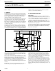
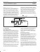
Philips Semiconductors Application note Using the NE/SA5234 amplifier AN1651 VIN VCC VIN VCC VOUT VCC VOUT 47k 5V 5V + – VIN VGND t VOUT t VGND 47k VGND CONVENTIONAL OP AMP PHILIPS NE5234 SL00569 non-inverting input. The output is taken from multiple collectors on the non-inverting side and provides matching for the following stage. 6 5 4 “N-MODE” CMRR VEE+1 < VCM < VCC 3 Class-AB control of the output stage is achieved by Q61 and Q62 with the associated output current regulators.
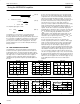
Philips Semiconductors Application note Using the NE/SA5234 amplifier AN1651 VCC D2 R82 IB5 IB2 Q83 IB6 IB4 R85 R76 Q81 Q85 IB8 – Q82 Q53,54 Q51,52 I2 Q84 C5 C3 INPUT OUTPUT C4 C6 Q72 + C2 I1 Q61 Q78 Q62 Q75 Q71 D3 VB4 CLASS AB CONTROL C1 IB3 IB7 R86 IB9 R75 VEE INTERMEDIATE STAGE CURRENT CONTROL CLASS AB OUTPUT SL00632 Figure 4. 100 80 dB 60 G1000 40 20 0 10Hz 100Hz 1kHz 10kHz 100kHz FREQUENCY Figure 5.
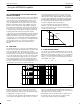
Philips Semiconductors Application note Using the NE/SA5234 amplifier AN1651 typically 0.2pA/√Hz. The 1/f region was not determined for either current or voltage noise. +2.5V 4 –2.5V 11 HP + 5234 – 600Ω 47k 10Ω 100 En for RS = 10Ω -nV/Hz 22 3585 nV SPECTRUM Ǹ Hz 95% 19 ANALYZER INT. x10 18 17 SL00634 Figure 6. Noise Test Circuit 16 100 200 2000 a. IV.
Philips Semiconductors Application note Using the NE/SA5234 amplifier AN1651 signal-to-noise ratio at the output of this stage is determined by first multiplying the gain times the signal which gives 1VRMS with a resultant noise of 400mVRMS. The signal-to-noise ratio is calculated as Sń N 20log 10 (1.0ń 4x10 * 4 ) + Sń N + This is quite adequate for good quality audio applications. en ƪ Ǹ 20x10 3 ƫ * * 3 (EQ. 7.) 4 56dB 1.6µV 100kΩ Next assume that the bandwidth is cut to 3.
Philips Semiconductors Application note Using the NE/SA5234 amplifier ƪǸ (0.163x10 * ǒǸ ) ) 3 2 4KT @ 100 @ 10, 000Ǔ + K + BoltzmanȀ sConstant + 1.38x10 * T + 23 2 ƫ @ 10 A series of tests are shown to allow you to see just how resistant this device is to generating clipping distortion. Two different gain configurations were chosen to demonstrate this particular feature: unity gain non-inverting and 40dB non-inverting. The test set-up was as shown in Figure 9.
Philips Semiconductors Application note Using the NE/SA5234 amplifier AN1651 aforementioned factors that affect the signal-to-noise ratio of the stage and optimizing the Loop-gain. For example, a voice-band audio stage which requires 3kHz bandwidth, should be limited to a closed-loop gain of 40dB for lowest distortion in the output signal. For higher quality audio applications requiring a 20kHz bandwidth, the closed-loop gain must be limited to 20dB.
Philips Semiconductors Application note Using the NE/SA5234 amplifier Slew Rate + V P (2p f) cos (2p AN1651 800,000 V/sec / 2π • 1.414 volts peak = 90,090Hz. A graphical representation of this relationship is shown in Figure 13. By using this graph along with the information in the preceding Figure 10 and Figure 11, which relate usable signal levels versus power supply voltage, the dynamic behavior of a particular design may be predicted.
Philips Semiconductors Application note Using the NE/SA5234 amplifier R 10k AN1651 R VCC V CC 2 4 CC + NE/SA5234 – A1 + T R A N S RS + A2 – RECEIVE UNIT 4700Ω – R1 RSH = 250Ω 11 C1 RF SL00644 SL00643 Figure 15. Non-Inverting Biasing Figure 16. A 4-20mA Current Loop 12k V2 1.2M 4.3k 4.3k |V2 – V1| 5.9mV VO 0.5V 25.6mV 2.50V 46.6mV 4.63V +5.0V S.G. 4 2 S.G. + +5.0V 4.3k 4.3k VO 1 – 3 1k 11 S.G.: Matched Strain Gauge elements 12k 1.2MΩ SL00645 Figure 17.
Philips Semiconductors Application note Using the NE/SA5234 amplifier AN1651 drive the current loop. The sensitivity is actually in mA/V, or transconductance, which is equal to 1/RSH. This sensitivity in this particular example is set to 4mA/V. Thus, with a bridge amplifier having a differential gain of 100, an input of 10mV will produce a 4mA output current and 50mV will produce a 20mA output.
Philips Semiconductors Application note Using the NE/SA5234 amplifier AN1651 20kΩ + A2 +4.5VDC – 10kΩ IC-1 NE5234 4 10Ω 0.1µF VR1 10Ω 0.1µF BDX45 VCC + + + 150 150 A3 A4 A1 – – – IC-2 NE5234 100kΩ VR2 10kΩ CL 150 + 150 A5 RS + VR2 A6 – – BDX42 CS VREF PM MOTOR 100 1 VR1-3 = 1.4V SL00648 Figure 20. Full Bridge Motor Drive audio impedance lines within a system. The use of two such amplifiers will provide stereo operation to +10dBm for a 600Ω load.
Philips Semiconductors Application note Using the NE/SA5234 amplifier AN1651 DC control signal is fed to A4 which acts as a threshold comparator with extremely high gain and controlled hysteresis. This provides a positive going signal for releasing the NE578 from its inhibit mode when voice input is present. The NE578 is switched from standby mode when voice input is present. The NE578 is switched from standby mode to the active state by raising the voltage on Pin 8 of the device above 2V.
Philips Semiconductors Application note Using the NE/SA5234 amplifier AN1651 +4.5V 10kΩ 10kΩ 10kΩ 4 NE5234 + – 19 16 12 100kΩ 1µF R3 + A2 – + A1 – 2.2kΩ 12kΩ +4.5V RA 11 18kΩ MIC NE578 SENS. ADJ. 25kΩ 0.15µF 220Ω 4.7µF RS D2 Ct RD 0.47µF 25kΩ D1 – A4 + + A3 – 11 1nF 9 8 4.2V 10kΩ X1 10 2.2MΩ OFF 0V 7 ON 40.2kΩ SL00651 Figure 23. VOX Audio System The compressor also has an attack time determined by capacitor C6 on Pin 11.
Philips Semiconductors Application note Using the NE/SA5234 amplifier AN1651 switching operation of the stage. However, care must be taken not allow the network’s time constant to become code dependent as to the average low frequency signal components or errors will result in the output signal. configuration and its output is squared to swing approximately 5V, the standard TTL level.
Philips Semiconductors Application note Using the NE/SA5234 amplifier AN1651 1 [ ]2 [ ]2 REL LEVEL INPUT TO ∆G VRMS +16dB 2.65V 1.67V 0dB AND RECT COMPRESSION IN (COMPRESSOR (EXPANDOR A OUT) IN) B C ABS LEVEL DB EXPANDOR OUT dBM D +16.0 +12.0 +10.68 +6.68 420mV 0.0 -5.32 -20dB 42mV -20 -25.32 -40dB 4.2mV -40 -45.32 -60 -65.32 -80 -85.32 -60dB 420µV -80dB 42µV TRANSMISSION MEDIUM SL00653 Figure 25.
Philips Semiconductors Application note Using the NE/SA5234 amplifier AN1651 +3V 4 1N9683 6 – 9 7 5 + – 8 10 + NE5234 2 – M 1N9683 13 – + 12 1 + 3 14 11 ÇÇÇÇÇ ÇÇ ÇÇÇÇ ÇÇÇÇÇ ÇÇ ÇÇÇÇ ÇÇÇÇÇ ÇÇ ÇÇÇÇ ÇÇ ÇÇÇÇ -3V 1/100 SL00655 Figure 27.